
351 Mod

Thread Starter
|
Senior Member
1st Gear Member
Joined: Jun 2008
Posts: 539
From: Saco, Maine
Well it's been a while since I've posted, although I've been lurking on a regular basis. Not much to contribute since we're in the dead of winter here and my bike is in the basement on a tender.
I think today is the day I will start my 351 conversion. I've had the kit since this past fall but have been way too busy to install it. I've got most of the things that I need except a torque wrench and some contact cleaner so today I hope to get through the "take it apart" phase. It will probably take me two weeks to get it back together since I have a busy schedule at work coming up.
I've never attempted anything this "mechanically inclined" before so wish me luck. If any of you have any tips, I'd love to hear them. Not just on how to do it but how to stay organized and make sure I don't end up with extra parts at the end
I also need to know what those of you at sea level did to the carb after installing the 351 kit. I've got the 128 needle and stock pilot jet right now. The rest of my carb settings are in my signature block. Can I leave it alone or do I need to change anything out?
I'm planning to do the carb breather mod at the same time as long as the whole thing is apart anyway.
I'm a little nervous but so far I've been able to do all the other mods to my bike relatively painlessly. I do have nobrakes very informative thread on how to do the mod to a 300cc jug so I plan to just follow it along with the manual. I'll try to take some pictures of the process so that we can get an updated thread with an '09 model. No promises, I may be all a$$holes and elbows once I get into it. Hopefully not.
Again, this forum is fantastic and thanks to all of you have given me the courage to do this!!

Senior Member
Joined: Jun 2008
Posts: 1,538
From: Connecticut
1st Gear Member
Take your time, follow that writeup, and you'll be fine.. Biggest thing is to *MAKE SURE YOUR TIMING IS CORRECT* before trying to start the motor for the first time. After you're sure it's correct, check it one more time. Or you can do like I did and throw a valve when it smacks on the new piston One new valve later and I learned my lesson 
Anyways, it's really easy, you should have no probs. Just check the timing, take your time, and all should be well.
For the jet kit - I'm around sea level too and the 132 seemed to be the right one. 132, stock pilot, 4th clip on the needle, and like 2 turns out on the air screw. Should be a decent baseline!!
Good luck! You can shoot me a PM if you have any Q's - I've had the motor apart on this bike more than a few times
One new valve later and I learned my lesson Anyways, it's really easy, you should have no probs. Just check the timing, take your time, and all should be well.
For the jet kit - I'm around sea level too and the 132 seemed to be the right one. 132, stock pilot, 4th clip on the needle, and like 2 turns out on the air screw. Should be a decent baseline!!
Good luck! You can shoot me a PM if you have any Q's - I've had the motor apart on this bike more than a few times
Thread Starter
|
Senior Member
1st Gear Member
Joined: Jun 2008
Posts: 539
From: Saco, Maine
Thanks guys, I'm taking a lunch break now. I've got everything off except the head off. I removed the four really tight head bolts, now I've just got the two smaller ones and the head should come off. I took a lot of really detailed pictures so I'll post them later today.
Also, Larry, on the timing... I have the timing check cover removed and I have a sideways T lined up with the notch. This was part of the removal process. Is this what you are talking about? I really have no clue how to time a bike...Will there be something I have to do when I put it back together? I'm hoping the manual will spell it out...
Also, Larry, on the timing... I have the timing check cover removed and I have a sideways T lined up with the notch. This was part of the removal process. Is this what you are talking about? I really have no clue how to time a bike...Will there be something I have to do when I put it back together? I'm hoping the manual will spell it out...
Senior Member
1st Gear Member
Joined: Oct 2007
Posts: 501
From: W. Oregon
When I do a job like this that I know is going to take longer than a few days I will sort the various bits and fasteners in logical groups and put them in baggies and label them with a sharpie. Comes in really handy when a job drags out or gets put off for whatever reason.
Thread Starter
|
Senior Member
1st Gear Member
Joined: Jun 2008
Posts: 539
From: Saco, Maine
HeavyFuel- I did the same thing. Each baggie has a piece of paper in it with the description of what parts/bolts are in there. Plus I wrote down each step I took so that I could put it back together in reverse. Hopefully it will end well
Thread Starter
|
Senior Member
1st Gear Member
Joined: Jun 2008
Posts: 539
From: Saco, Maine
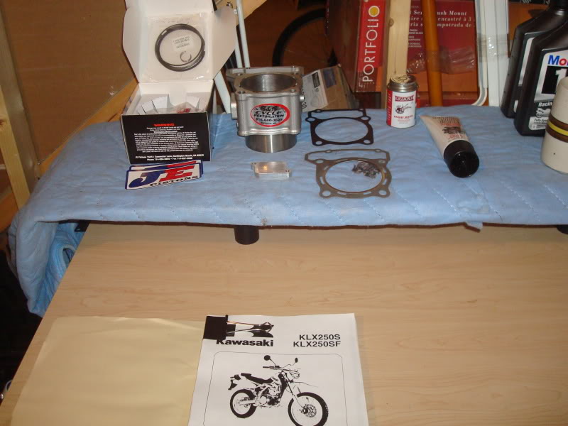
Ok, the teardown went pretty well. Not nearly as bad as I thought it would. I am no expert so use these pictures at your own risk!
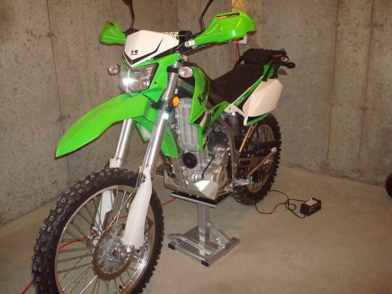
Here is the patient before the elective surgery. It runs great... for now...
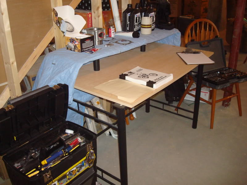
Here is my little work area
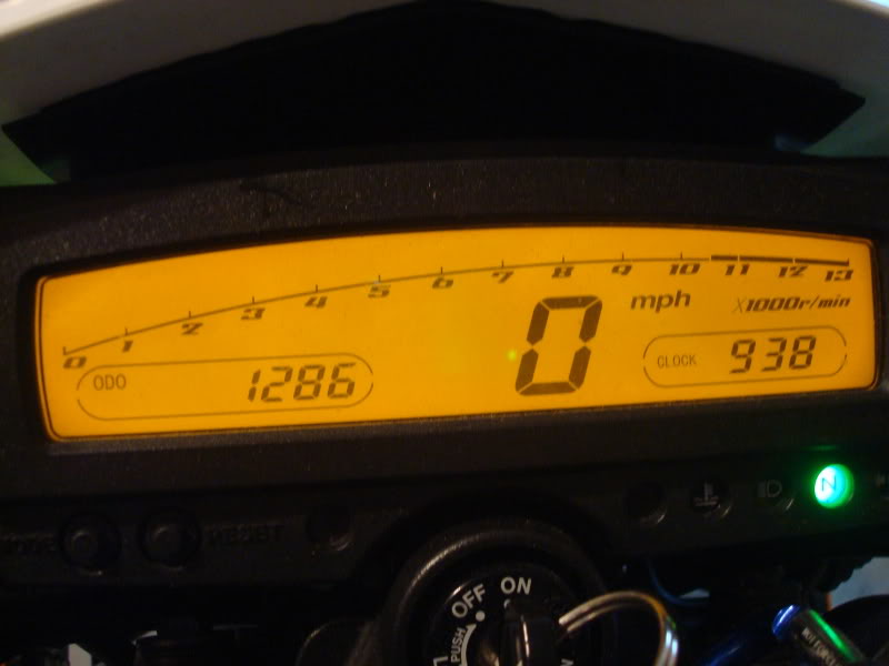
Had to take a picture of the odometer. Poor thing only has 1200 miles. It's still a baby!
Ok, first step is to take off the seat and the 6 bolts that hold it on. Unfortunately the two hex bolts that hold on my nomad rack are starting to rust. I guess I'll need to replace them.
Then remove the shrouds and the six 8mm bolts that hold them on.
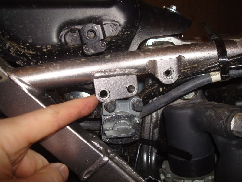
Then I disconnected the fuel petcock from the frame (2 bolts) and disconnected the fuel hose from the carbuerator. This will allow me to pull the tank. After the petcock is discontinued, remove the three bolts that hold the tank on.
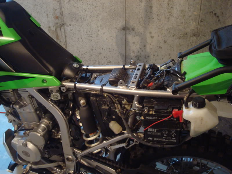
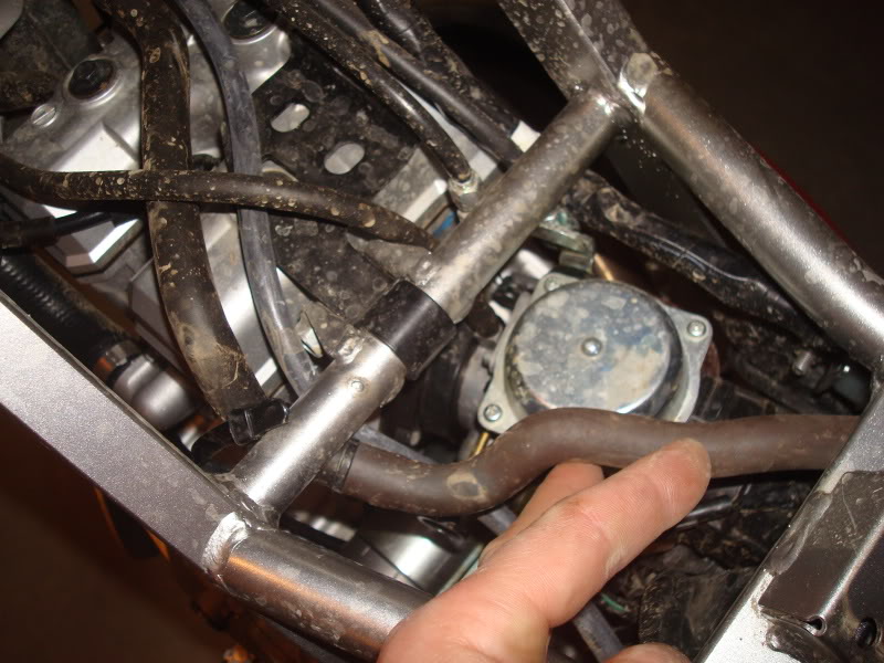
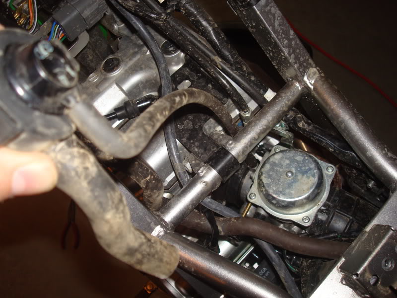
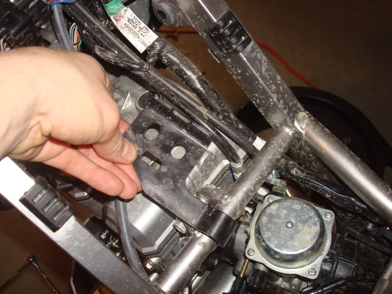
Then I removed the vacuum switch valve. You have to remove it from the frame and then there are three hose connections. 1 to the front of the engine, one to the airbox, and one to the carb. Not sure if I'll put this back on.
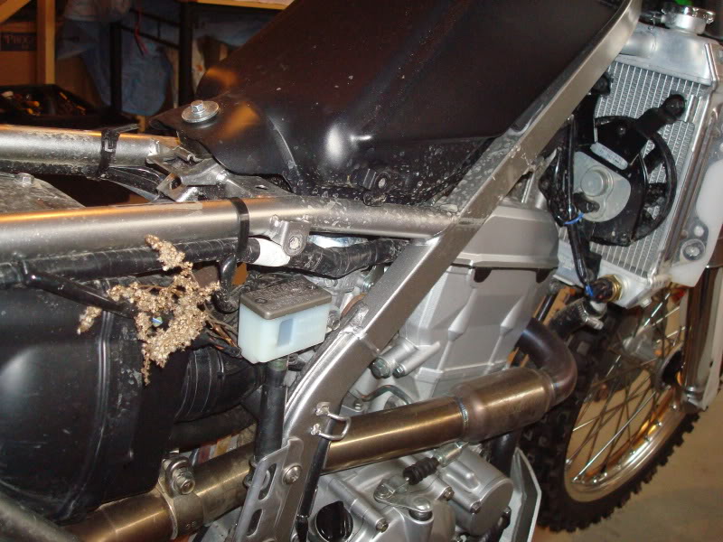
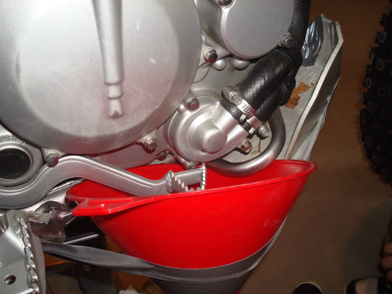
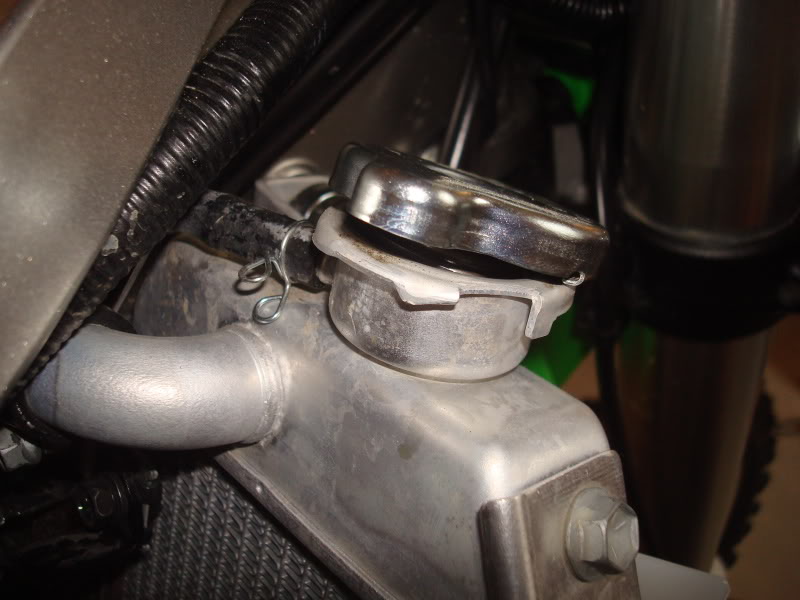
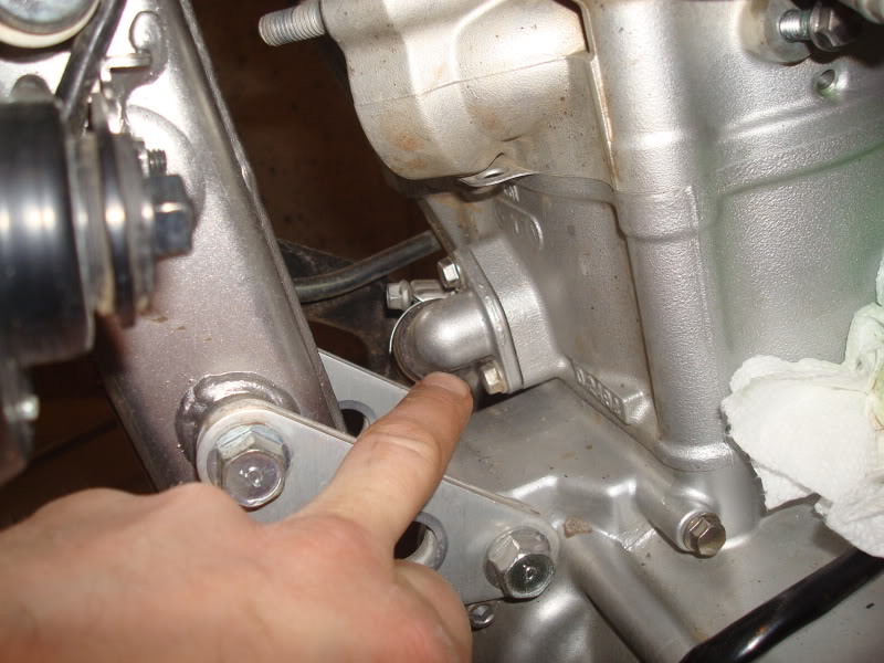
After draining the oil, I set to work draining the coolant. Note how I mounted the funnel. There is a small bolt underneath the water pump that will drain out the coolant. I found a technique that worked pretty well for this. After the bolt is removed, not a lot of water comes out. Then, you slowly unscrew the radiator cap and let a little air in. The coolant will come out in a controlled manner as long as you control the amount of air you let into the radiator. Otherwise, it will come gushing out fast and make a huge mess. The mess I made with this technique was very minimal.
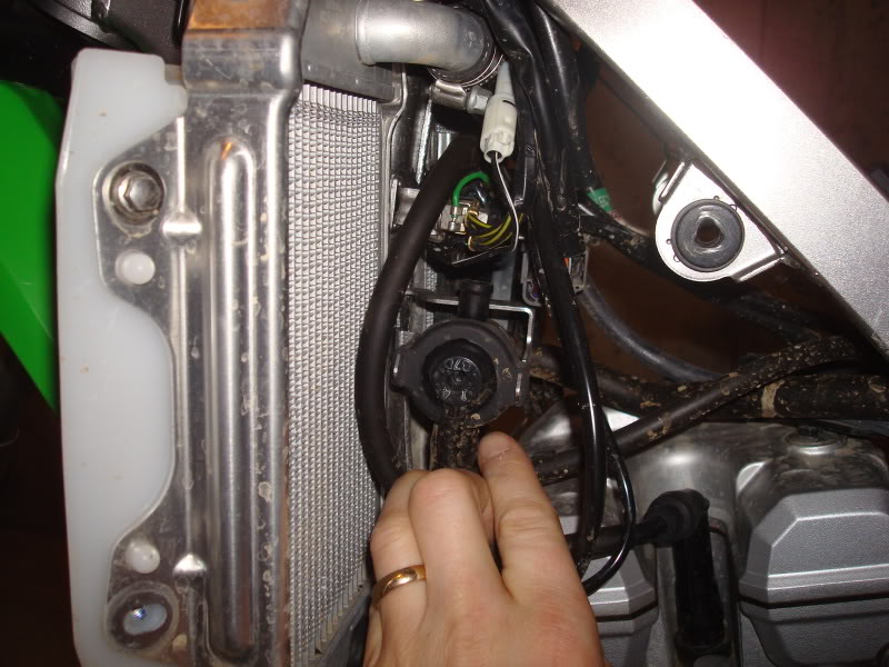
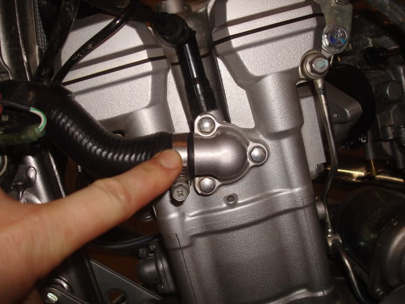
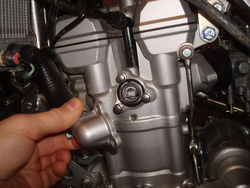
Then I disconnected the coolant hose from the engine. This is where the thermostat is located. I think there was some loctite on these bolts so I'll be sure to put some back on when I put it back together.
Then I removed the black plastic guard thingy from above the cylinder. Not sure what its called but it clips to the frame and protects the hoses.
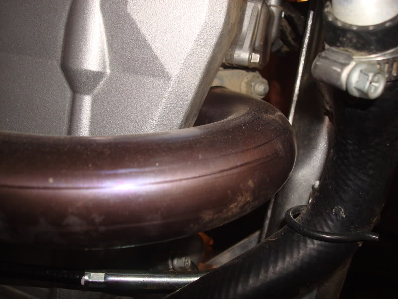
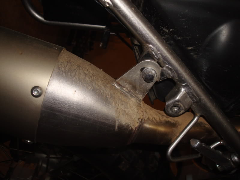
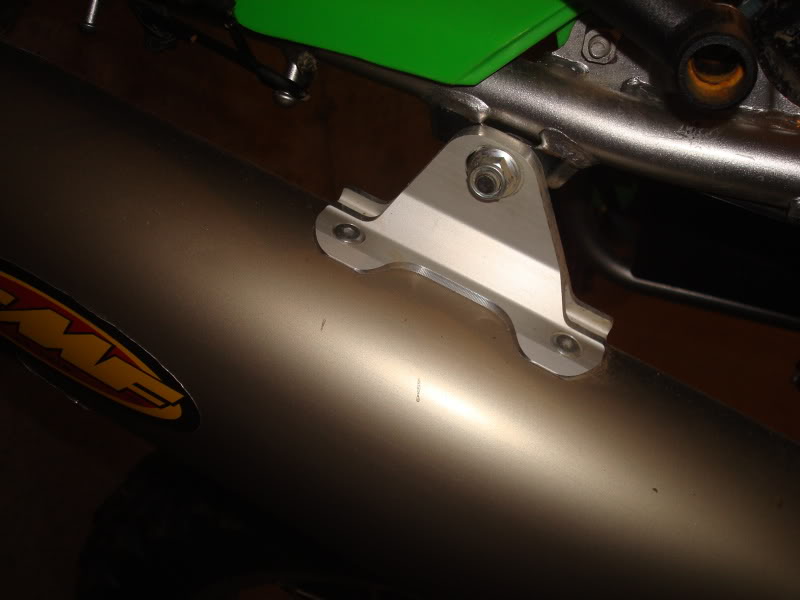
Then I removed the muffler and head pipe. This proved difficult as the silicone bond between the two was tough to break. Love the FMF and Powerbomb header!
Then I removed the coolant hose from the front of the engine.
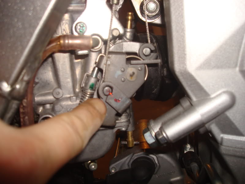
Now it's time to pull the carb. Since I've had this out before, I knew the importance of marking the throttle cables...
More to follow...
Here is the patient before the elective surgery. It runs great... for now...
Here is my little work area
Had to take a picture of the odometer. Poor thing only has 1200 miles. It's still a baby!
Ok, first step is to take off the seat and the 6 bolts that hold it on. Unfortunately the two hex bolts that hold on my nomad rack are starting to rust. I guess I'll need to replace them.
Then remove the shrouds and the six 8mm bolts that hold them on.
Then I disconnected the fuel petcock from the frame (2 bolts) and disconnected the fuel hose from the carbuerator. This will allow me to pull the tank. After the petcock is discontinued, remove the three bolts that hold the tank on.
Then I removed the vacuum switch valve. You have to remove it from the frame and then there are three hose connections. 1 to the front of the engine, one to the airbox, and one to the carb. Not sure if I'll put this back on.
After draining the oil, I set to work draining the coolant. Note how I mounted the funnel. There is a small bolt underneath the water pump that will drain out the coolant. I found a technique that worked pretty well for this. After the bolt is removed, not a lot of water comes out. Then, you slowly unscrew the radiator cap and let a little air in. The coolant will come out in a controlled manner as long as you control the amount of air you let into the radiator. Otherwise, it will come gushing out fast and make a huge mess. The mess I made with this technique was very minimal.
Then I disconnected the coolant hose from the engine. This is where the thermostat is located. I think there was some loctite on these bolts so I'll be sure to put some back on when I put it back together.
Then I removed the black plastic guard thingy from above the cylinder. Not sure what its called but it clips to the frame and protects the hoses.
Then I removed the muffler and head pipe. This proved difficult as the silicone bond between the two was tough to break. Love the FMF and Powerbomb header!
Then I removed the coolant hose from the front of the engine.
Now it's time to pull the carb. Since I've had this out before, I knew the importance of marking the throttle cables...
More to follow...
Last edited by armycopter; Feb 28, 2010 at 06:15 PM.
Thread Starter
|
Senior Member
1st Gear Member
Joined: Jun 2008
Posts: 539
From: Saco, Maine
Remove the head cover and the three bolts that hold it on.
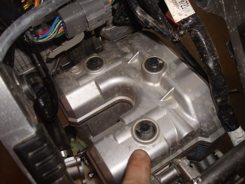
Now we're into unknown territory. Not sure what to expect but it looks pretty good to me.
Then I disconnected the oil routing tube.
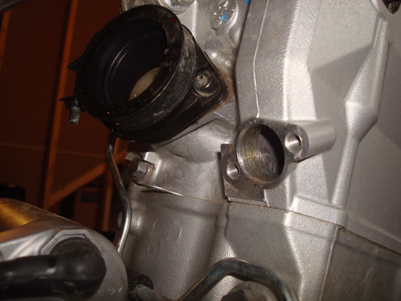
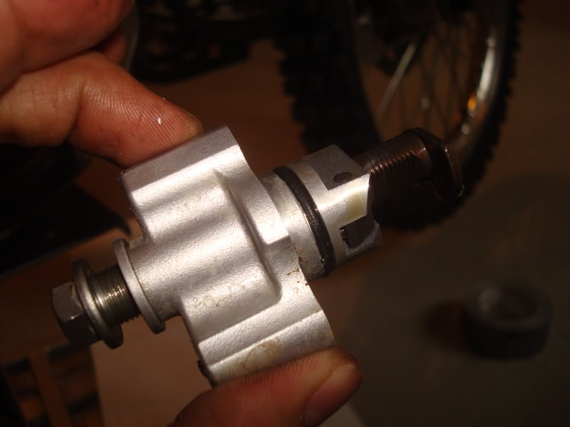
Then remove the cam chain tensioner and sub chain tensioner.
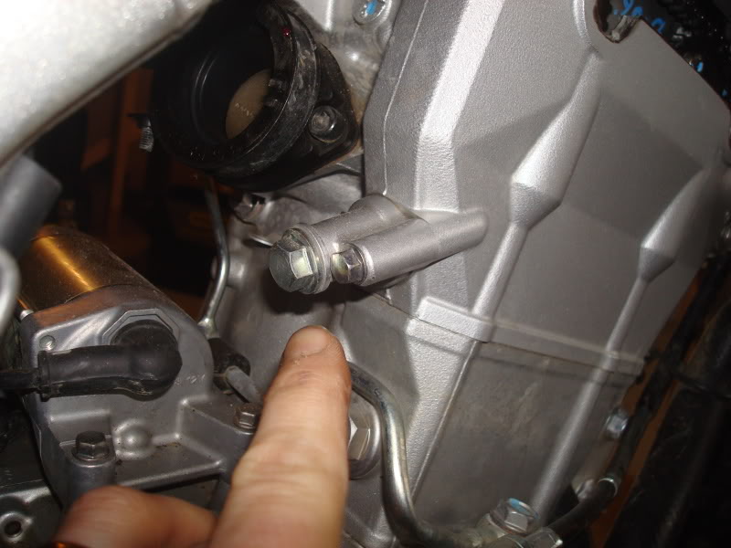
the sub chain tensioner
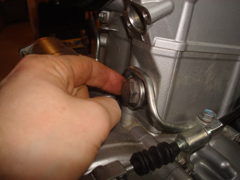
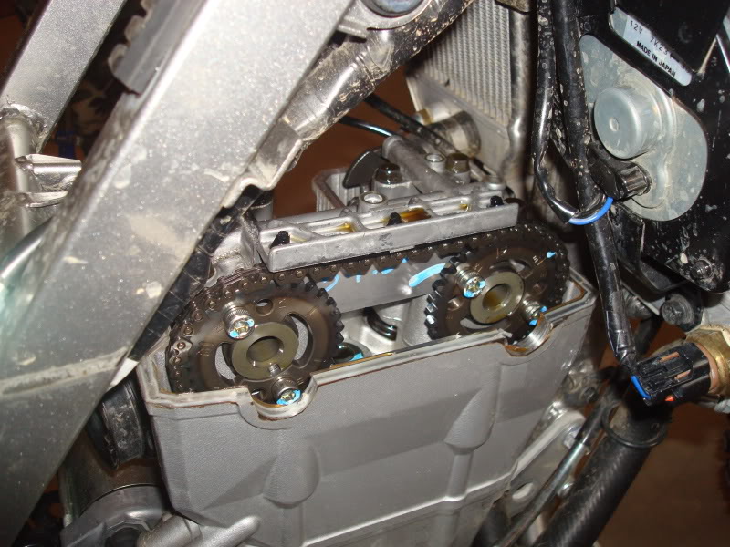
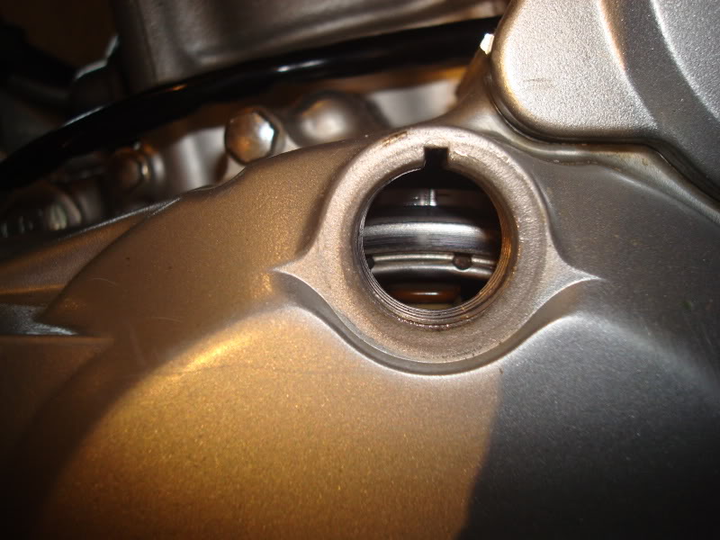
Then remove the timing inspection cap and rotor bolt cap. It says a special tool is needed but a screwdriver works fine. You have to align the camshaft "T" with the notch in the timing inspection cap at this point. I guess that puts the piston at TDC. Not sure...

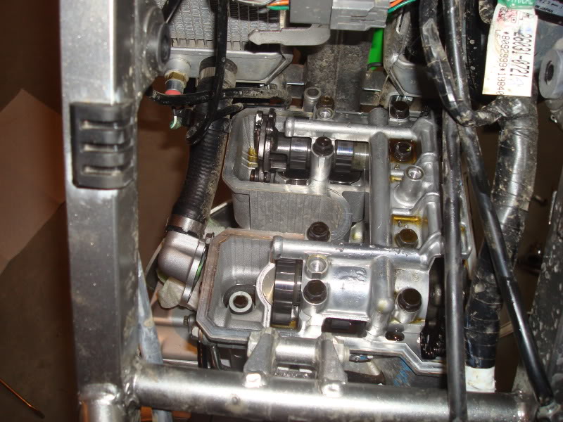
Now remove the camshaft cap bolts (eight) and camshaft cap.
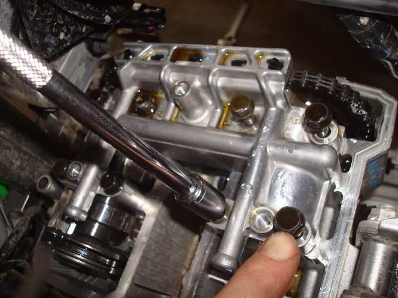
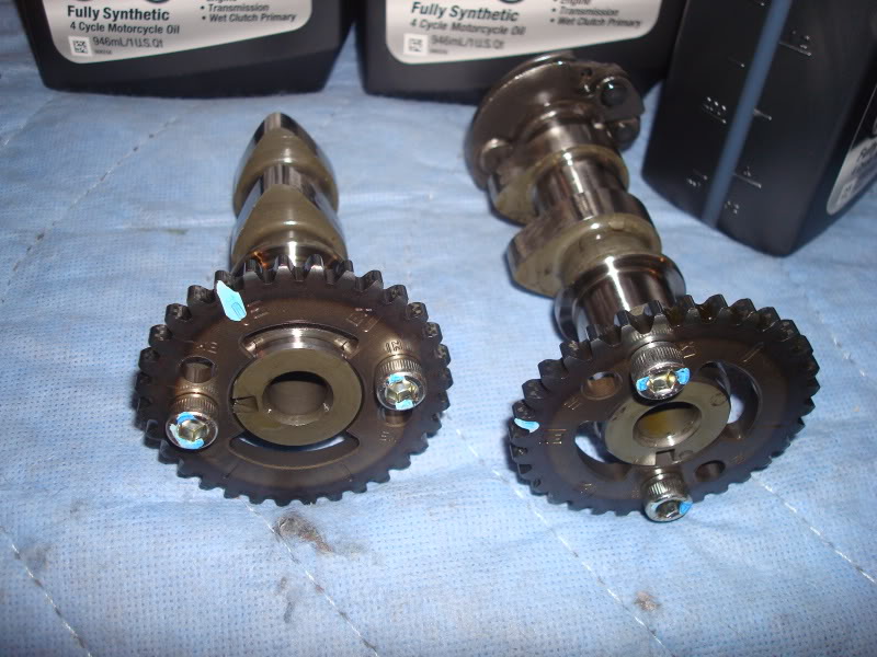
Out come the cams!
more to follow...
Now we're into unknown territory. Not sure what to expect but it looks pretty good to me.
Then I disconnected the oil routing tube.
Then remove the cam chain tensioner and sub chain tensioner.
the sub chain tensioner
Then remove the timing inspection cap and rotor bolt cap. It says a special tool is needed but a screwdriver works fine. You have to align the camshaft "T" with the notch in the timing inspection cap at this point. I guess that puts the piston at TDC. Not sure...
Now remove the camshaft cap bolts (eight) and camshaft cap.
Out come the cams!
more to follow...
Senior Member
Joined: Mar 2008
Posts: 3,406
From: N. Illinois
1st Gear Member
Army, Good Luck!! I'm in the same boat as you as far as engine work experience, and I've been contemplating buying the 351. I have pretty much justified the cost, but don't want the cost to triple when I screw something up . Shortening my fuel range is another concern, but, the extra power might overshadow that. Please do take lots of pics and post em up. It would be nice to have a good mod day thread on the 351 kit. BB could babysit some of us and put a step by step how to on his site. Here's one tip,Again I'm no expert , and this may only matter when checking the valve clearance but I think you want the piston at TDC with both the valves closed. (it's possible to have that "T" mark lined up with one set of valves or the other open). Sombody with more knowledge please confirm this. Here's what the manual says. (again this may only be the case if you are checking the valves)
Git er done.
Dan
From the manual.
Check the valve clearance when piston is at TDC.
• Using a wrench on the crankshaft rotation bolt [D],turn the crankshaft counterclockwise while watching the movement of inlet valves (valves to rear). When the valves have just finished opening and closing (moving downwards and returning upwards), turn the crankshaft in the same direction about another 1/2 turn until the "T" mark [B] on the magneto flywheel is aligned with the notch [A] on the upper hole of the magneto cover [C].
At this point, the marks on the camshaft sprockets point forward and line up with the surface of the cylinder head.
. Shortening my fuel range is another concern, but, the extra power might overshadow that. Please do take lots of pics and post em up. It would be nice to have a good mod day thread on the 351 kit. BB could babysit some of us and put a step by step how to on his site. Here's one tip,Again I'm no expert , and this may only matter when checking the valve clearance but I think you want the piston at TDC with both the valves closed. (it's possible to have that "T" mark lined up with one set of valves or the other open). Sombody with more knowledge please confirm this. Here's what the manual says. (again this may only be the case if you are checking the valves)Git er done.
Dan
From the manual.
Check the valve clearance when piston is at TDC.
• Using a wrench on the crankshaft rotation bolt [D],turn the crankshaft counterclockwise while watching the movement of inlet valves (valves to rear). When the valves have just finished opening and closing (moving downwards and returning upwards), turn the crankshaft in the same direction about another 1/2 turn until the "T" mark [B] on the magneto flywheel is aligned with the notch [A] on the upper hole of the magneto cover [C].
At this point, the marks on the camshaft sprockets point forward and line up with the surface of the cylinder head.
Thread Starter
|
Senior Member
1st Gear Member
Joined: Jun 2008
Posts: 539
From: Saco, Maine
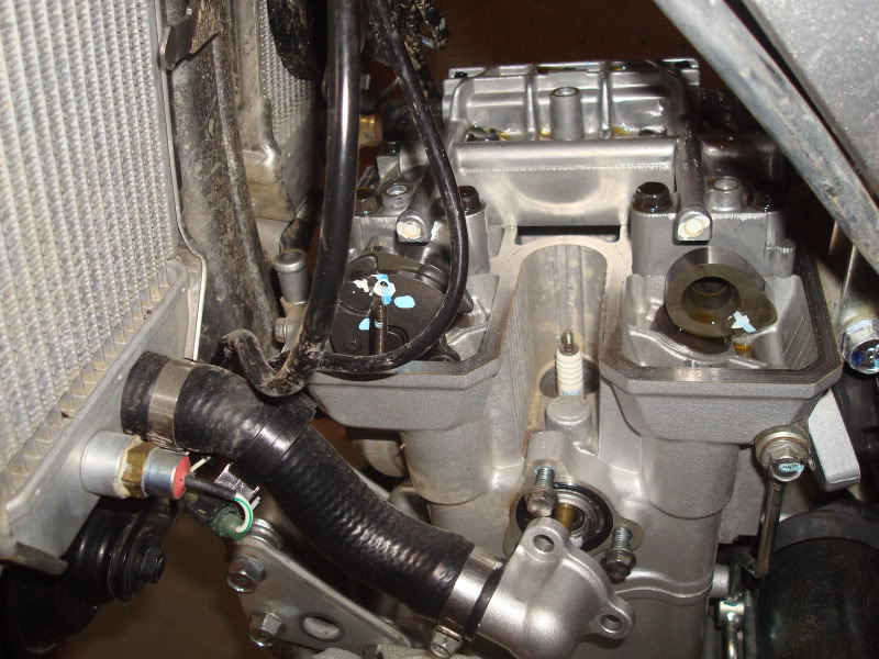
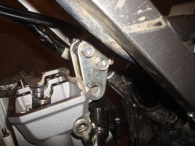
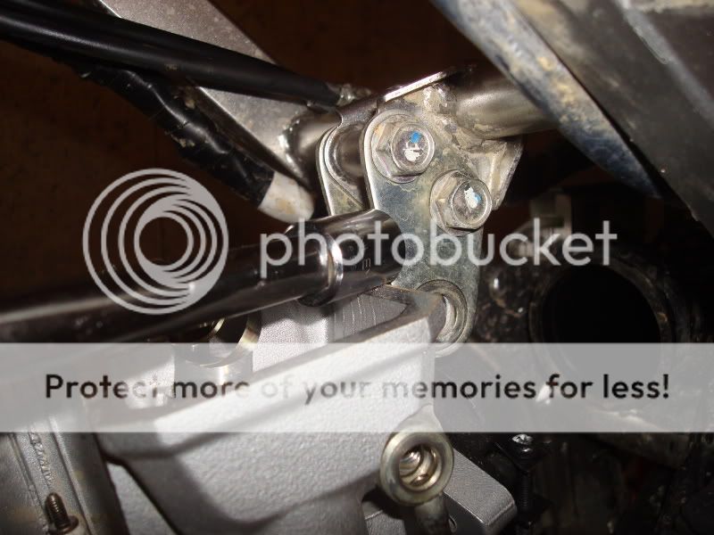
and then there are four very tight head bolts. Take these out, along with the two smaller ones near the chain.
Remove the upper engine mount bracket
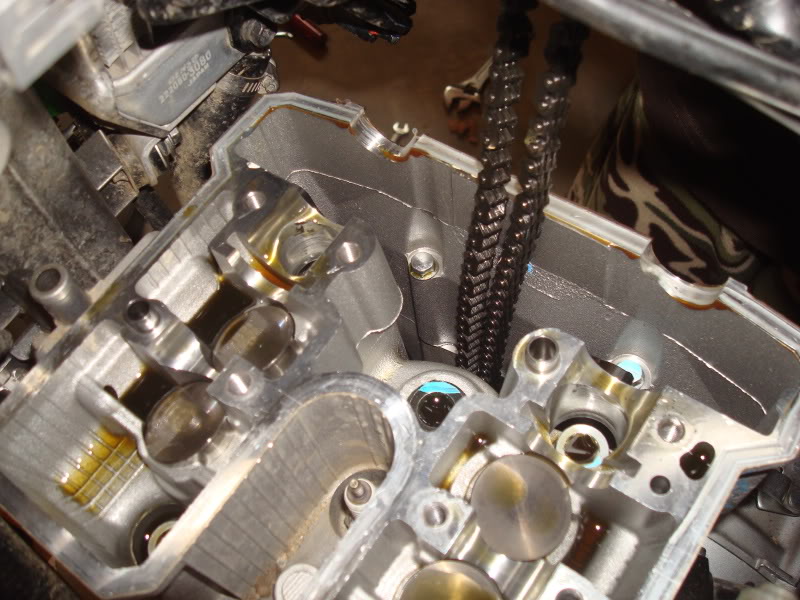
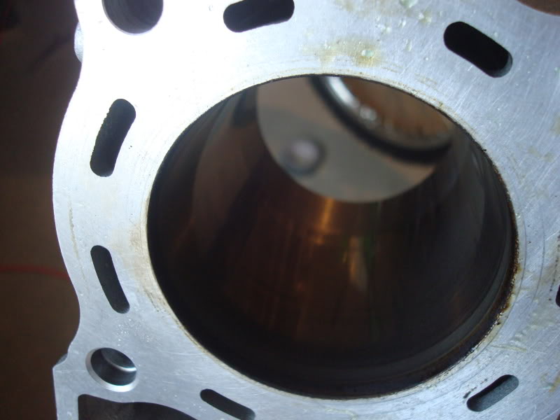
Then the head comes right off. Careful not to drop the chain down into the lower unit.
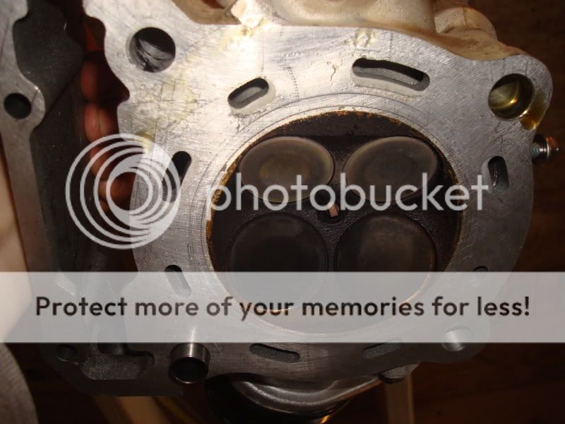
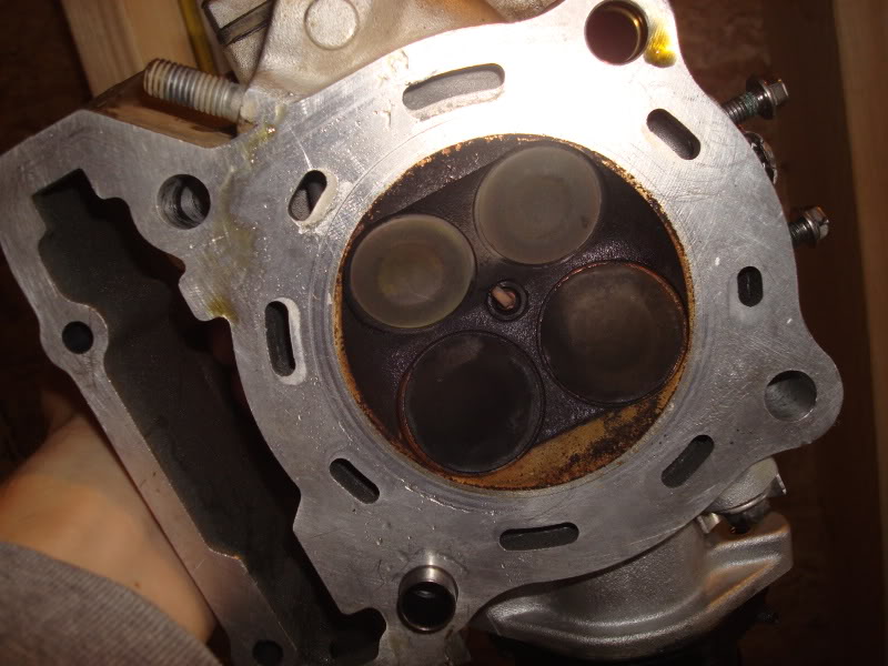
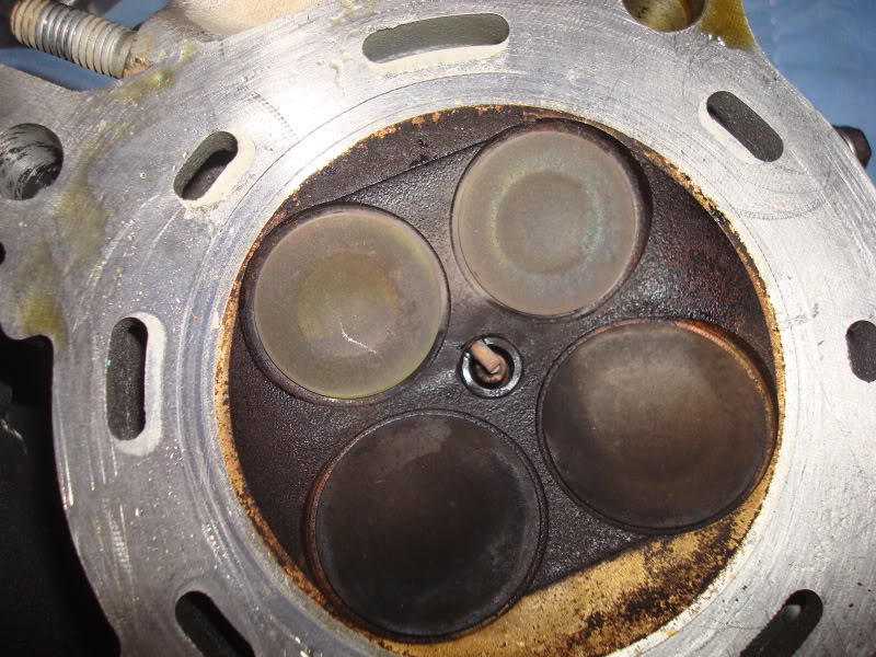
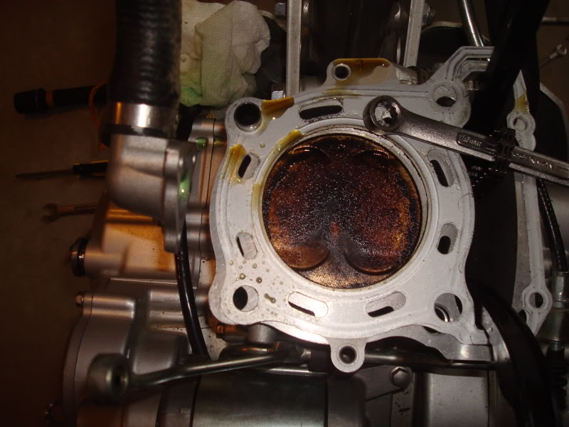
There is the top of my cylinder! Doesn't look too bad.
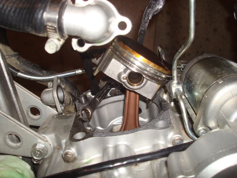
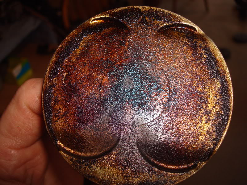
Then pull the retaining clip so you can get the piston out. Notice that the arrow on the piston points forward. Good info for the re-install.
Cylinder and piston look fine.
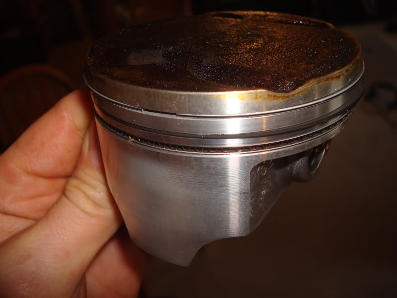
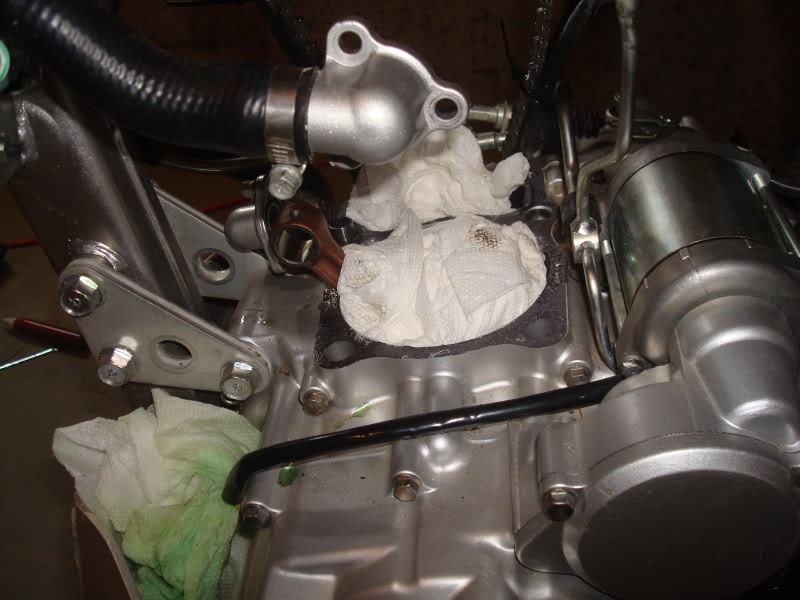
Cover everything up and wait for the re-assembly!
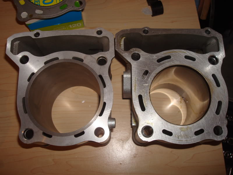
250 vs. 351
Can't wait to get it together. Any thoughts on whether I should put the vacuum switch valve back on?
Remove the upper engine mount bracket
Then the head comes right off. Careful not to drop the chain down into the lower unit.
There is the top of my cylinder! Doesn't look too bad.
Then pull the retaining clip so you can get the piston out. Notice that the arrow on the piston points forward. Good info for the re-install.
Cylinder and piston look fine.
Cover everything up and wait for the re-assembly!
250 vs. 351
Can't wait to get it together. Any thoughts on whether I should put the vacuum switch valve back on?