
Wiring up switch in place of key/ignition


Thread Starter
|
Senior Member
1st Gear Member
Joined: Jun 2011
Posts: 592
1st Gear Member
Gents...been through this one and my setup works.
I believe the diagram may be for an Aus bike, '06 or newer (duh) with a park circuit. My '06 doesn't have a park circuit. But remove the park portion and it's the same. With the double throw switch, think of it as on-on, or perhaps A-B (where some circuits are connected in 'A' and others in 'B' positions). I believe a park circuit would need a triple throw (on-off-on). My switch is a 3PDT I believe...it has a total of 9 pins. The double throw portion I think is for the security resistor circuit. But I'm not using it that way, and am only using 6 of the 9 pins (three in the middle & three on the bottom connected, three on the top are unused). I could have used a 3PST.
I believe the diagram may be for an Aus bike, '06 or newer (duh) with a park circuit. My '06 doesn't have a park circuit. But remove the park portion and it's the same. With the double throw switch, think of it as on-on, or perhaps A-B (where some circuits are connected in 'A' and others in 'B' positions). I believe a park circuit would need a triple throw (on-off-on). My switch is a 3PDT I believe...it has a total of 9 pins. The double throw portion I think is for the security resistor circuit. But I'm not using it that way, and am only using 6 of the 9 pins (three in the middle & three on the bottom connected, three on the top are unused). I could have used a 3PST.
Also, did you just cut the wires from right below where they come out of the black ignition cylinder or did you take that cylinder apart once you had it removed from the bike?
Believe it or not, I have actually had it mounted in a secondary location allowing me to keep the key and the X2 and vapor until I had a chance to change out the key for a toggle.
Senior Member
Joined: Oct 2010
Posts: 4,507
From: SW Idaho
1st Gear Member
Thanks Scott, so when you say that you are not using the security resistor circuit, do you have the 100 ohm resistor wired in at all?
Also, did you just cut the wires from right below where they come out of the black ignition cylinder or did you take that cylinder apart once you had it removed from the bike?
Believe it or not, I have actually had it mounted in a secondary location allowing me to keep the key and the X2 and vapor until I had a chance to change out the key for a toggle.
After taking the cylinder apart I just CUT the wires so I could tell where they went if I ever needed to put it back together.
Last edited by IDRIDR; Jun 1, 2012 at 02:47 PM. Reason: added "CUT"
Thread Starter
|
Senior Member
1st Gear Member
Joined: Jun 2011
Posts: 592
1st Gear Member
You NEED the 100 ohm resistor. My understanding from others is that it will not work without it. That's one of the circuits switched on my bike, and I think instead it could be wired in parallel with the Bk/Y & Bk/W wires. I'm pretty sure one could use a 2PST switch for this system, and I plan to do that in the future to reduce bulk (4 pin switch instead of 9). I'd always intended on putting the 100-ohm circuit onto a hidden switch of its own for improved security, but decided a big lock works fine for me. Maybe another day.
After taking the cylinder apart I just the wires so I could tell where they went if I ever needed to put it back together.
After taking the cylinder apart I just the wires so I could tell where they went if I ever needed to put it back together.
How did you take the cylinder apart itself?
I would rather not take it apart if I don't have to and just grab a resistor elsewhere
Senior Member
Joined: Oct 2010
Posts: 4,507
From: SW Idaho
1st Gear Member
"Cut" the wires (edited earlier post). No need to take the cylinder apart. I drilled out some screws in it. Get a 100 ohm resistor from Radio Shack or similar.

Senior Member
Joined: Jul 2011
Posts: 1,728
From: Cottonwood, AZ USA
1st Gear Member
I would suggest not getting a "2P" or "ST" switch as the "OFF&LOCK: BK/Y TO BK/W" require these wires to make in one position (OFF), and the other pairs of wires to make when in the other (ON) position.
Draw a little wiring diagram or look at the one posted. How in the world are you going to get a 2PST switch to make the wiring connections?
With the problems understanding this my suggestion is you need to get some help from someone that is more knowledgable in wiring circuitry like a hobbist/electrican.
Get the 3PDT switch.
Senior Member
Joined: Oct 2010
Posts: 4,507
From: SW Idaho
1st Gear Member
One of those Aus fellers is great at electronics...wish he would chime in. But as I look at the diagram and based on my own experience with the switch, the off position is essentially bypassing the resistor as it makes a direction connection between Bk(Y) & Bk(W); I believe this is for security / hotwire reduction. The on position opens the direct Bk(Y)/Bk(W) circuit, engages the resistor in the Bk(Y)/Bk(W) circuit, and makes the power connections. I'm convinced this can be done with a 2PST. My 3PDT switch has NO connections on one side (not using the 2nd half of the double throw capability), and I've made it work with only four wires connected (hence, 2PST) while just keeping the resistor circuit hard wired in place. Try it! Why not?
I'm an amateur, did take two semesters of Engineering Circuitry, did not stay in a Holiday Inn last night, and of course, YRMV!
I'm an amateur, did take two semesters of Engineering Circuitry, did not stay in a Holiday Inn last night, and of course, YRMV!
Last edited by IDRIDR; Jun 2, 2012 at 01:58 AM. Reason: changed: The on position closes the direct to "opens"
Thread Starter
|
Senior Member
1st Gear Member
Joined: Jun 2011
Posts: 592
1st Gear Member
Scott - I picked up a 2PST and a 3PDT today. I'm going to give it a try this evening.
By the way, any chance that you remember the size of the holes on the triple clamp that you screwed your fabricated bracket onto for the vapor? I'm guessing 10MM but I haven't looked yet.
By the way, any chance that you remember the size of the holes on the triple clamp that you screwed your fabricated bracket onto for the vapor? I'm guessing 10MM but I haven't looked yet.
Senior Member
Joined: Oct 2010
Posts: 4,507
From: SW Idaho
1st Gear Member
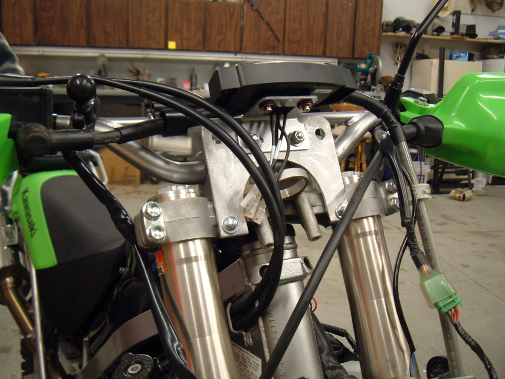
Don't remember the size ... just some of the extras I had laying around that fit. One flat piece of aluminum and connected to some of the stocker headlight holes. The headlight went away for an X2. Inserted ignition and headlight (on/off) switches into the holes you see on either side of the Vapor.
Last edited by IDRIDR; Jun 1, 2012 at 10:53 PM.