[AUS] DIY Shock and Fork revalve/service
#1
 07-20-2014, 03:47 AM


Shock dissassembly and stock valving
I figured that even if I don't know what new valving I am going to want to put into the bike yet, I am still going to have to take the stock shock apart - so why not do it this morning? So I whipped out my Racetech Motorcycle Suspension Bible and flicked to the "Reservoir Shocks" project section (page 200 if you have the book) and followed the steps detailed there. I tell you what, all those detailed pictures detailing every step of what you have to do is worth its weight in gold! Seriously, it gives even a gumby like me the confidence that I am doing the correct thing.
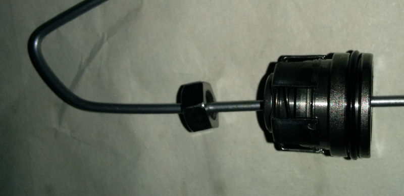
Now, my KLX shock doesn't have a valve like most shocks - it requires the use of a needle to puncture the bladder to release the gas and recharge it. With the pressure released I pulled out a nice big socket and the rubber mallet to smack the reservoir cap down so I could remove the circlip. It required a fair whack to shift the cap down and immediately oil leaked up and made a mess on my floor.
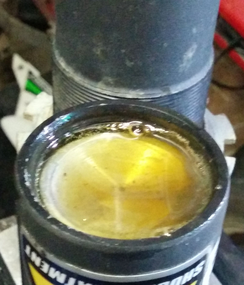
I dug the circlip out and pulled the cap and bladder. If the cap has a valve it is pretty simple to pull it off because you have something to pull on, or you can blow some air into the bladder to make it pop off. Because my cap doesn't have a valve it took a little more fiddling around but it came off easy enough in the end.
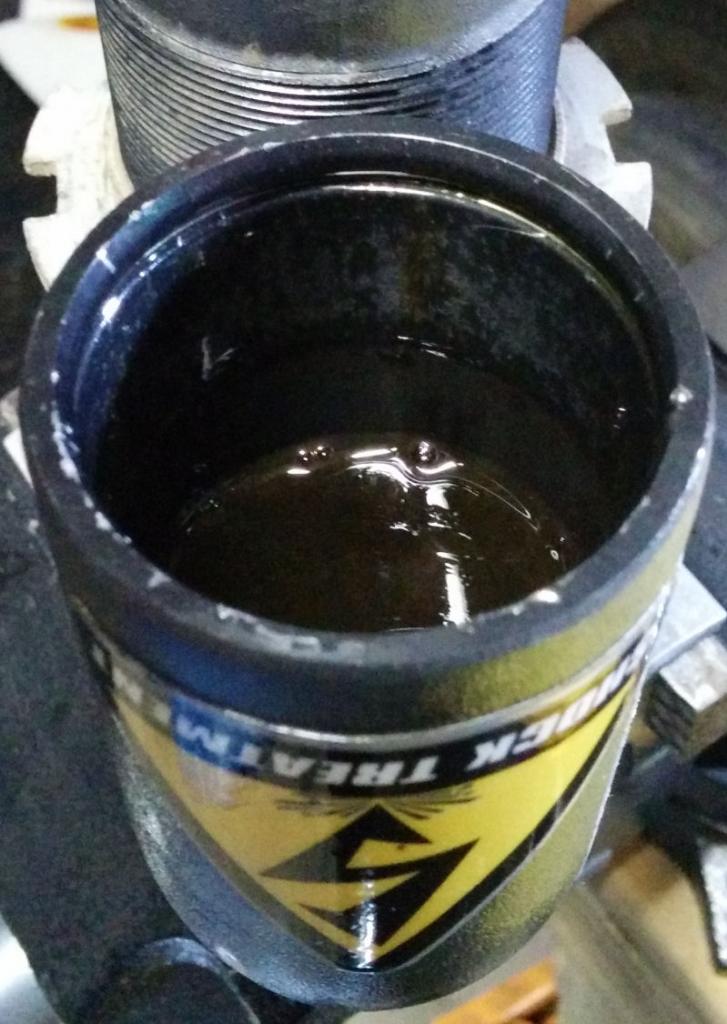
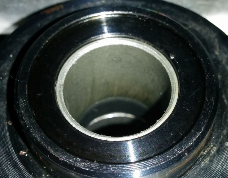
Inspecting the inside of the reservoir I noted that there was a bit of scuffing on the inside near the edge - I don't expect that is a problem though as this shock uses a bladder rather than a piston that needs to seal against the sidewall in order to maintain pressure.
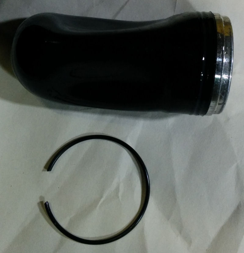
From there it was just a case of using a gasket scraper and rubber mallet to pop off the shock body cap to expose the head seal. Pushing that down with my finders was easy enough to expose the circlip holding it in. Out with the circlip and then a couple of light taps with a rubber mallet and the shaft popped out. I poured the oil out and was and left the shock body upside down to drain it whilst I worked on the shaft.
"The bible" now tells you to file off the peening using a file. Now, I was a little to cautious doing this and didn't file enough. I only realised this when I started unwinding the nut and it was quite stiff - I thought I was just overcoming some loctite but soon realised what I was doing was pushing the peening up!
So I got filing again until it was easier to remove the nut from the shock shaft. With the nut removed I cleaned up the end of shaft as per the instructions and blasted out the hole in the centre shaft with compressed air to clean it up. With that done I removed the seal head, body cap, bottom out bumper, and retaining cup.
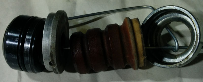
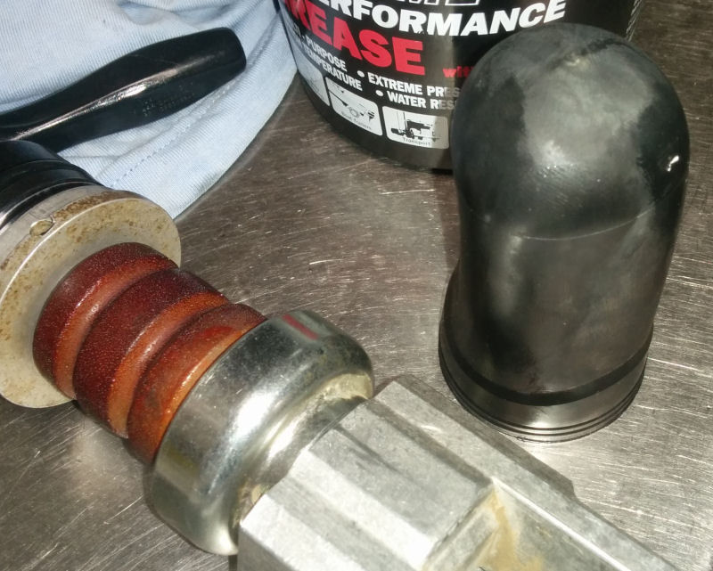
That bottom out bumper is looking tired so I will be getting a new one I think. With that all off I inspected the shaft and noticed it is VERY smooth and shiney! I need to get myself some 500 or 600 grit sandpaper to "dress" it and get some cross-hatching on it so that it seals like it should. Otherwise the shaft looks in pretty good condition (in my uneducated opinion anyway).
Next it was time to remove the seals from the seal head and inspect the bush. The seal and bush on this shock are still the original ones from when I bought the bike back in 2010 so I figured they would need replacing even if they looked ok. As it turns out the shock shaft bush looks like it is ready to be replaced anyway. The seal looked OK but it is a quick, cheap, and easy part to replace to save myself regretting on changing it down the line.
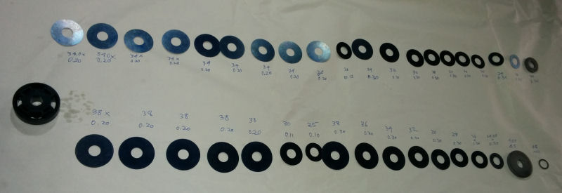
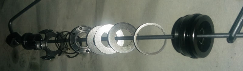
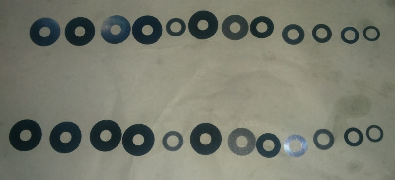
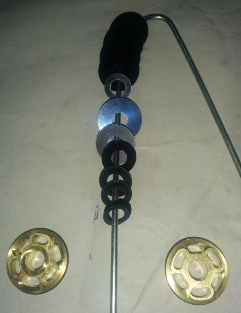
Now to the "fun" part - I cleaned the valving stack in some degreaser and then laid it all out on a piece of butchers paper (saved packing from a previous Rockey Mountain order). I suddenly felt all "professional" seeing it all laid out. Cracked out the verniers and measured each shim as Terry had shown me before and wrote down each measurement (diameter and thickness).
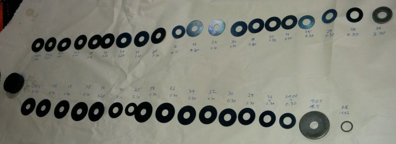
So, I think the valving stacks are as follows (but I am open to correction):
Compression
38 x 0.20 x 5
30 x 0.10
25 x 0.10
38 x 0.30
36 x 0.30
34 x 0.30
32 x 0.30
30 x 0.30
28 x 0.30
26 x 0.30
24 x 0.30
Rebound
34 x 0.20 x 9
26 x 0.10
34 x 0.30
23 x 0.30
30 x 0.30
28 x 0.30
27 x 0.30
26 x 0.30
25 x 0.30
24 x 0.30
23 x 0.30
So if I am correct this means the stock valving is 2 stage compression stack with a pretty stiff first stage (5 shims), and a 3 stage rebound with a VERY stiff first stage (9 shims!). I have a lot to learn in this area though so I will be interested to see what shim stacks Racetechs advises for me.
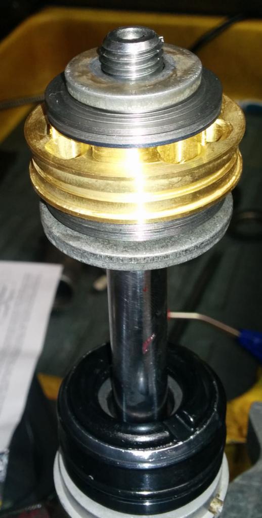
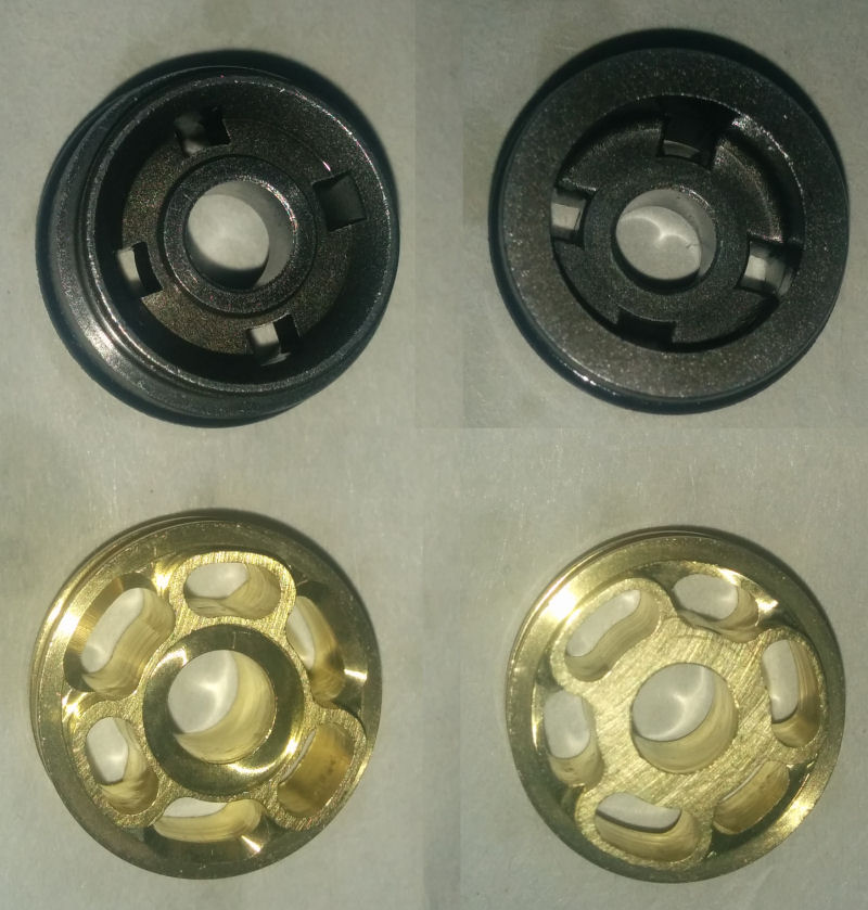
As a matter of interest is the stock piston (black one on the left) next to the Racetech Gold piston. I think there is some significance to do with the fact that the stock pistons ports are opposite each other (allowing the shims to "fold" easier and hence provide inconsistent damping) versus the Racetech one having the ports staggered in such a way that the fluid is forced across 3 different points around the shim, none of which are directly opposite one another so the shim should flex evenly. Again, I have a lot to learn in this regard so don't take that as gospel.
So now I am am just waiting to find out what shim stacks I need to put together and I can go about trying to put everything back together again. Because I don't have a stanard valve on the reservoir cap I cannot inflate it myself with plain air. I did note that the Racetech kit said that you can use plain air but they advise nitrogen.
Now I'm debating tearing down the forks as well... this is addictive!
I figured that even if I don't know what new valving I am going to want to put into the bike yet, I am still going to have to take the stock shock apart - so why not do it this morning? So I whipped out my Racetech Motorcycle Suspension Bible and flicked to the "Reservoir Shocks" project section (page 200 if you have the book) and followed the steps detailed there. I tell you what, all those detailed pictures detailing every step of what you have to do is worth its weight in gold! Seriously, it gives even a gumby like me the confidence that I am doing the correct thing.
Now, my KLX shock doesn't have a valve like most shocks - it requires the use of a needle to puncture the bladder to release the gas and recharge it. With the pressure released I pulled out a nice big socket and the rubber mallet to smack the reservoir cap down so I could remove the circlip. It required a fair whack to shift the cap down and immediately oil leaked up and made a mess on my floor.
I dug the circlip out and pulled the cap and bladder. If the cap has a valve it is pretty simple to pull it off because you have something to pull on, or you can blow some air into the bladder to make it pop off. Because my cap doesn't have a valve it took a little more fiddling around but it came off easy enough in the end.
Inspecting the inside of the reservoir I noted that there was a bit of scuffing on the inside near the edge - I don't expect that is a problem though as this shock uses a bladder rather than a piston that needs to seal against the sidewall in order to maintain pressure.
From there it was just a case of using a gasket scraper and rubber mallet to pop off the shock body cap to expose the head seal. Pushing that down with my finders was easy enough to expose the circlip holding it in. Out with the circlip and then a couple of light taps with a rubber mallet and the shaft popped out. I poured the oil out and was and left the shock body upside down to drain it whilst I worked on the shaft.
"The bible" now tells you to file off the peening using a file. Now, I was a little to cautious doing this and didn't file enough. I only realised this when I started unwinding the nut and it was quite stiff - I thought I was just overcoming some loctite but soon realised what I was doing was pushing the peening up!
So I got filing again until it was easier to remove the nut from the shock shaft. With the nut removed I cleaned up the end of shaft as per the instructions and blasted out the hole in the centre shaft with compressed air to clean it up. With that done I removed the seal head, body cap, bottom out bumper, and retaining cup.
That bottom out bumper is looking tired so I will be getting a new one I think. With that all off I inspected the shaft and noticed it is VERY smooth and shiney! I need to get myself some 500 or 600 grit sandpaper to "dress" it and get some cross-hatching on it so that it seals like it should. Otherwise the shaft looks in pretty good condition (in my uneducated opinion anyway).
Next it was time to remove the seals from the seal head and inspect the bush. The seal and bush on this shock are still the original ones from when I bought the bike back in 2010 so I figured they would need replacing even if they looked ok. As it turns out the shock shaft bush looks like it is ready to be replaced anyway. The seal looked OK but it is a quick, cheap, and easy part to replace to save myself regretting on changing it down the line.
Now to the "fun" part - I cleaned the valving stack in some degreaser and then laid it all out on a piece of butchers paper (saved packing from a previous Rockey Mountain order). I suddenly felt all "professional" seeing it all laid out. Cracked out the verniers and measured each shim as Terry had shown me before and wrote down each measurement (diameter and thickness).
So, I think the valving stacks are as follows (but I am open to correction):
Compression
38 x 0.20 x 5
30 x 0.10
25 x 0.10
38 x 0.30
36 x 0.30
34 x 0.30
32 x 0.30
30 x 0.30
28 x 0.30
26 x 0.30
24 x 0.30
Rebound
34 x 0.20 x 9
26 x 0.10
34 x 0.30
23 x 0.30
30 x 0.30
28 x 0.30
27 x 0.30
26 x 0.30
25 x 0.30
24 x 0.30
23 x 0.30
So if I am correct this means the stock valving is 2 stage compression stack with a pretty stiff first stage (5 shims), and a 3 stage rebound with a VERY stiff first stage (9 shims!). I have a lot to learn in this area though so I will be interested to see what shim stacks Racetechs advises for me.
As a matter of interest is the stock piston (black one on the left) next to the Racetech Gold piston. I think there is some significance to do with the fact that the stock pistons ports are opposite each other (allowing the shims to "fold" easier and hence provide inconsistent damping) versus the Racetech one having the ports staggered in such a way that the fluid is forced across 3 different points around the shim, none of which are directly opposite one another so the shim should flex evenly. Again, I have a lot to learn in this regard so don't take that as gospel.
So now I am am just waiting to find out what shim stacks I need to put together and I can go about trying to put everything back together again. Because I don't have a stanard valve on the reservoir cap I cannot inflate it myself with plain air. I did note that the Racetech kit said that you can use plain air but they advise nitrogen.
Now I'm debating tearing down the forks as well... this is addictive!
#3
07-20-2014, 04:31 AM
Join Date: Jan 2010
Location: kootenay country BC Canada
Posts: 1,800
Quote - Now I'm debating tearing down the forks as well... this is addictive! - Quote
Wait until the shock is back together? Not quite as many pieces laying around that way.
Great write-up/how-to!!
Wait until the shock is back together? Not quite as many pieces laying around that way.
Great write-up/how-to!!
#5
07-22-2014, 09:04 AM
So, I though I had made a decent start to the revalving work on my shock yesterday, but a few things just weren't sitting right with me and some unanswered questions that made me uneasy with carrying on without some professional advice.
- I felt the bush inside the seal head was very tight against the shock shaft
- I had not changed the seals as the dust seal that I had was the wrong size, and I could not figure out how to remove the large washer covering the oil seal in order to remove and replace it
- There were 4 shims that I needed in the valving stack that were not in the Racetech kit - I didn't know whether they were missing for a reason (e.g. the valving chart had been changed and differed from the shims provided) or whether it was OK to re-use shims out of the original stack (I though there was a possibility that re-using shims was not advised because they fatigue)
- The reservoir bladder was partially inflated only and I wasn't sure if I needed to have it fully deflated or inflated before starting the oil bleeding process
- There was a small washer below the large thick washer on the original stack that was not on any diagrams from Racetech so I did not know whether I should remove it or leave it in place
- I thought the rubber bottom-out stopper was looking tired and needed replacing, and I didn't have a new part on hand
Knowing that I did not have any meetings scheduled at work today and that there was little chance of me being able to focus with these questions in my head. So I asked my boss for the day off and armed with my questions, my suspension bible, my shock in bits, and all the parts from the Racetech kit I drove over to Shock Treatment to see if I could get answers to my questions. What a great decision that was!
Let me just put this out there right now - Shock Treatment ROCK! Grant really did a great job fixing my mistakes, teaching me what I had done wrong, and the right way to do stuff.
So what did I do wrong and what should I have done?
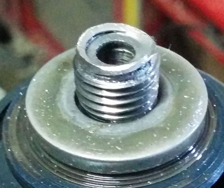
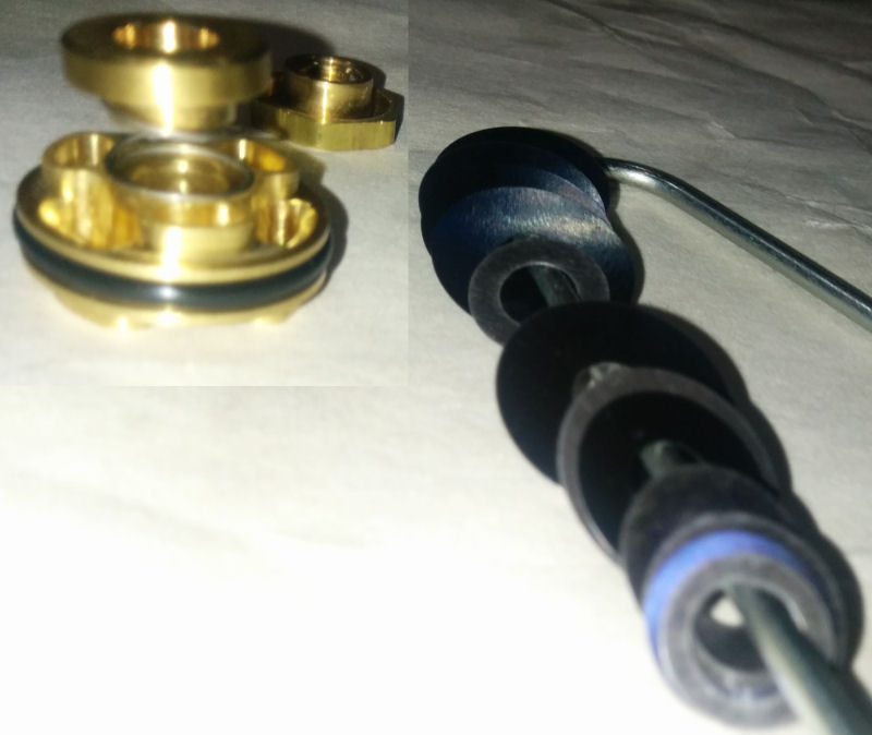
Well, I was right in thinking that the seal head was too tight on the shaft. Turns out that I had damaged the internal wall of the hole the bush was pressed into, so there were a couple of small bumps on the surface that effectively pushing on the bush which made it tight on the shaft. I had tried to remove the old bush using a punch and digging it into the bush wall to pierce the teflon coating, bite into the bush and push it out. Although this was the right idea the problem is I did not hold the punch more upright after it had bitten into the bush, so when I was hammering the bush wasn't coming out. So I resorted to trying to catch the top edge of the bush with the punch... BIG NO-NO! Not only did this do some damage to the top of the seal head it also damaged the wall the bush presses up against. This is why there is something to be said for getting professionals to do the job if you are a gumby! The yellow arrows show the damage I did.
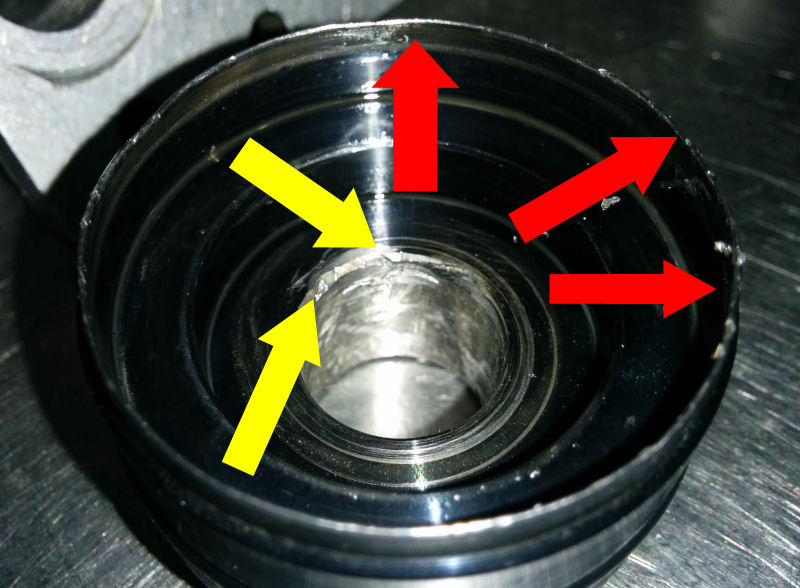
As it turns out, I did not need to use a punch to remove the bush anyway. All I needed to do was put a large socked in the vice then put the seal head onto the socket (with the large washer covering the oil seal on top of the socket) and tap around the edge with a mallet to straighten out the "folded in" lip on the seal head in order to remove the washer. The Red arrows in the above image show the lip that was straightened out and the washer removed. With the oil seal exposed it is easy to remove the bush by putting the right size bush-press in and tapping it out with a hammer. When I saw Grant do that I felt like a right idiot!
So that kind of answered my second question anyway, as now it was simple to change the oil seal. Turns out my shock is rather unusual as most shocks have a top-out spring and/or bumper that holds the seal in place without the edge of the seal head needing to be folded over. Anyway, I have learned something new. The rest of the 2nd question I had was answered when it turned out I had bought the wrong dust seal, so that is why it didn't fit. I presume this has something to do with the difference between the Aussie shock and the USA model.
As for the 3rd question, apparently sometimes the Racetech kit is missing a few shims if there are shims in the original stack that can be re-used. So I plucked the 4 shims I needed out of the original stack and put them in the right position in the new stack - too easy!
As for the reservoir bladder being partially inflated, that is how it is meant to be. You don't want to fully inflated as it will push too much oil out when you insert it, and you don't want it totally deflated because then it will leave too much oil in the reservoir which could cause problems when pressurizing the bladder.
And finally, the small washer below the large washer is there as a spacer and it needed to be retained, and my bottom-out rubber was still fine. It had a bit of "bounce" to it when compressed, and there were no cracks that could end up with fluid in them - apparently if the rubber is cracked they fail quite spectacularly if called upon to stop the shock from bottoming out.
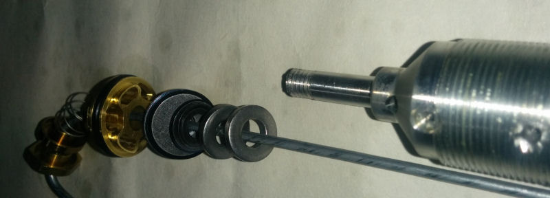
With all my questions answered (plus a whole lot more that I asked whilst there) and my damage repaired we finally got around to putting the valving stack on - ready to start the oil bleeding process. Notice how the valve stack comes up to the shaft threads so that the nut will hold the shim stack firmly in place. If the valving stack does not come up to the threads you need to put a spacer in so that the nut will place pressure on the shim stack and hold it to the piston face.
With the bleeding I opted to do it manually rather than use the vacuum bleeder as I do not have a vacuum bleeder and don't think I could justify the cost of getting one for the frequency I am likely to be servicing my shock. The Racetech bible gives very clear instructions on how to do the bleeding and I found it easy to follow. That being said, I did get a few helpful hints from Grant whilst I did the bleeding. I put the shock into the vice with the 2 opening facing upwards and poured fluid into the reservoir till it was about 15mm below the lip of the reservoir. Without wasting much time, as fluid starts leaking through into the shock body straight away, I pushed the bladder into the reservoir. There was a good amount of overflow so I knew there was no air in the reservoir. I pushed the cap down far enough to put the circlip in to hold it in place. As it turns out, I put the circlip that was meant for the shock body in the reservoir, so be sure you don't make the same mistake if you do this yourself. It is easy enough to rectify, but it is an unnecessary annoyance.
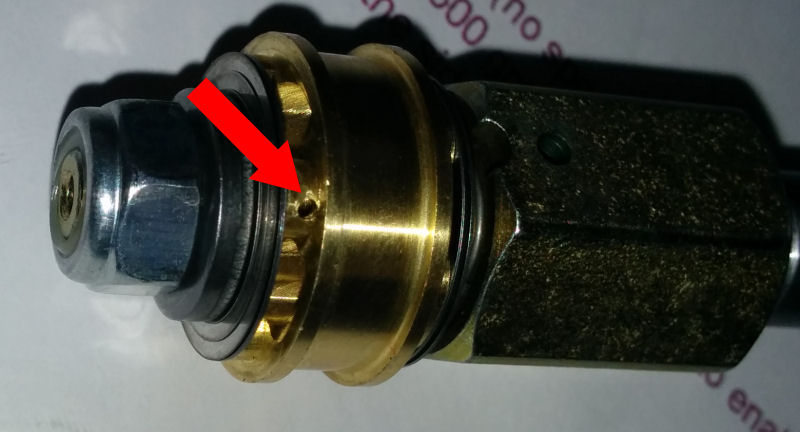
With the circlip in place a little air was needed in the bladder to pop the cap back up against the ciclip. Because my shock doesn't have a valve it needs a syringe needle to be pushed through the small hole in the cap which has a rubber bung underneath it. Well, when I pushed the needle into the rubber bung it popped out of its hole, so we had to remove the cap again, glue the rubber bung in and then use a centre punch to "gently" peen around the bung-hole edge to make sure that the bung stays in place. It seemed to do the trick.
Time to fill the shock body with fluid to about 40mm from the top and then insert the shock shaft. Just a word of warning though - as you push the valve piston into the shock body there might be a sudden spurt of fluid out the edge and/or hole in the side of the shaft which can make quite a mess. With the piston it, I topped the oil off and then started pumping the shock shaft up and down slowly. At first I made the mistake of pulling the shaft too far up and it sucked some air in the shaft bleed hole. Once I figured out how high to pull the shaft up I stroked it down fast then up slowly (to avoid airating the oil under the piston in the shock body). Once no more air bubbles were coming up it was time to use a hammer to smack the top of the shaft as it was being pushed down to force any air left trapped in or behind the shims. The first 2 or 3 times I did this air bubble came out, but then the next few times there was nothing so the bleeding was complete.
I pushed the seal head in and then with the needle in the bladder to allow air to escape I pressed the seal head down till in was past the circlip groove and put the circlip in. The bladder was then slightly pressurised to push the seal cap up against the circlip nice and firm. With that done the shock body cap way tapped into place with a plastic mallet, then the shaft was pushed all the way down whilst the needle was in the bladder to release the air in the bladder. If there was any air left in the bladder is was a negligible amount. The bladder was then charged with 175psi of nitrogen, then the shaft was pressed in and released to rise from the pressure in the shock. There were no gurgling sounds or anything so we were confident that the air was properly bled out the system, and the shaft returned to a fully extended position on its own. SWEET! Time to put the spring back on and put the shock back in the bike.
With the linkage off I took advantage of having easy access to the linkage bearings by packing them with fresh marine grease before bolting everything back up. I'll have to set the sag when everything is back together, but otherwise the rear is done!
Now onto the forks...
- I felt the bush inside the seal head was very tight against the shock shaft
- I had not changed the seals as the dust seal that I had was the wrong size, and I could not figure out how to remove the large washer covering the oil seal in order to remove and replace it
- There were 4 shims that I needed in the valving stack that were not in the Racetech kit - I didn't know whether they were missing for a reason (e.g. the valving chart had been changed and differed from the shims provided) or whether it was OK to re-use shims out of the original stack (I though there was a possibility that re-using shims was not advised because they fatigue)
- The reservoir bladder was partially inflated only and I wasn't sure if I needed to have it fully deflated or inflated before starting the oil bleeding process
- There was a small washer below the large thick washer on the original stack that was not on any diagrams from Racetech so I did not know whether I should remove it or leave it in place
- I thought the rubber bottom-out stopper was looking tired and needed replacing, and I didn't have a new part on hand
Knowing that I did not have any meetings scheduled at work today and that there was little chance of me being able to focus with these questions in my head. So I asked my boss for the day off and armed with my questions, my suspension bible, my shock in bits, and all the parts from the Racetech kit I drove over to Shock Treatment to see if I could get answers to my questions. What a great decision that was!
Let me just put this out there right now - Shock Treatment ROCK! Grant really did a great job fixing my mistakes, teaching me what I had done wrong, and the right way to do stuff.
So what did I do wrong and what should I have done?
Well, I was right in thinking that the seal head was too tight on the shaft. Turns out that I had damaged the internal wall of the hole the bush was pressed into, so there were a couple of small bumps on the surface that effectively pushing on the bush which made it tight on the shaft. I had tried to remove the old bush using a punch and digging it into the bush wall to pierce the teflon coating, bite into the bush and push it out. Although this was the right idea the problem is I did not hold the punch more upright after it had bitten into the bush, so when I was hammering the bush wasn't coming out. So I resorted to trying to catch the top edge of the bush with the punch... BIG NO-NO! Not only did this do some damage to the top of the seal head it also damaged the wall the bush presses up against. This is why there is something to be said for getting professionals to do the job if you are a gumby! The yellow arrows show the damage I did.
As it turns out, I did not need to use a punch to remove the bush anyway. All I needed to do was put a large socked in the vice then put the seal head onto the socket (with the large washer covering the oil seal on top of the socket) and tap around the edge with a mallet to straighten out the "folded in" lip on the seal head in order to remove the washer. The Red arrows in the above image show the lip that was straightened out and the washer removed. With the oil seal exposed it is easy to remove the bush by putting the right size bush-press in and tapping it out with a hammer. When I saw Grant do that I felt like a right idiot!
So that kind of answered my second question anyway, as now it was simple to change the oil seal. Turns out my shock is rather unusual as most shocks have a top-out spring and/or bumper that holds the seal in place without the edge of the seal head needing to be folded over. Anyway, I have learned something new. The rest of the 2nd question I had was answered when it turned out I had bought the wrong dust seal, so that is why it didn't fit. I presume this has something to do with the difference between the Aussie shock and the USA model.
As for the 3rd question, apparently sometimes the Racetech kit is missing a few shims if there are shims in the original stack that can be re-used. So I plucked the 4 shims I needed out of the original stack and put them in the right position in the new stack - too easy!
As for the reservoir bladder being partially inflated, that is how it is meant to be. You don't want to fully inflated as it will push too much oil out when you insert it, and you don't want it totally deflated because then it will leave too much oil in the reservoir which could cause problems when pressurizing the bladder.
And finally, the small washer below the large washer is there as a spacer and it needed to be retained, and my bottom-out rubber was still fine. It had a bit of "bounce" to it when compressed, and there were no cracks that could end up with fluid in them - apparently if the rubber is cracked they fail quite spectacularly if called upon to stop the shock from bottoming out.
With all my questions answered (plus a whole lot more that I asked whilst there) and my damage repaired we finally got around to putting the valving stack on - ready to start the oil bleeding process. Notice how the valve stack comes up to the shaft threads so that the nut will hold the shim stack firmly in place. If the valving stack does not come up to the threads you need to put a spacer in so that the nut will place pressure on the shim stack and hold it to the piston face.
With the bleeding I opted to do it manually rather than use the vacuum bleeder as I do not have a vacuum bleeder and don't think I could justify the cost of getting one for the frequency I am likely to be servicing my shock. The Racetech bible gives very clear instructions on how to do the bleeding and I found it easy to follow. That being said, I did get a few helpful hints from Grant whilst I did the bleeding. I put the shock into the vice with the 2 opening facing upwards and poured fluid into the reservoir till it was about 15mm below the lip of the reservoir. Without wasting much time, as fluid starts leaking through into the shock body straight away, I pushed the bladder into the reservoir. There was a good amount of overflow so I knew there was no air in the reservoir. I pushed the cap down far enough to put the circlip in to hold it in place. As it turns out, I put the circlip that was meant for the shock body in the reservoir, so be sure you don't make the same mistake if you do this yourself. It is easy enough to rectify, but it is an unnecessary annoyance.
With the circlip in place a little air was needed in the bladder to pop the cap back up against the ciclip. Because my shock doesn't have a valve it needs a syringe needle to be pushed through the small hole in the cap which has a rubber bung underneath it. Well, when I pushed the needle into the rubber bung it popped out of its hole, so we had to remove the cap again, glue the rubber bung in and then use a centre punch to "gently" peen around the bung-hole edge to make sure that the bung stays in place. It seemed to do the trick.
Time to fill the shock body with fluid to about 40mm from the top and then insert the shock shaft. Just a word of warning though - as you push the valve piston into the shock body there might be a sudden spurt of fluid out the edge and/or hole in the side of the shaft which can make quite a mess. With the piston it, I topped the oil off and then started pumping the shock shaft up and down slowly. At first I made the mistake of pulling the shaft too far up and it sucked some air in the shaft bleed hole. Once I figured out how high to pull the shaft up I stroked it down fast then up slowly (to avoid airating the oil under the piston in the shock body). Once no more air bubbles were coming up it was time to use a hammer to smack the top of the shaft as it was being pushed down to force any air left trapped in or behind the shims. The first 2 or 3 times I did this air bubble came out, but then the next few times there was nothing so the bleeding was complete.
I pushed the seal head in and then with the needle in the bladder to allow air to escape I pressed the seal head down till in was past the circlip groove and put the circlip in. The bladder was then slightly pressurised to push the seal cap up against the circlip nice and firm. With that done the shock body cap way tapped into place with a plastic mallet, then the shaft was pushed all the way down whilst the needle was in the bladder to release the air in the bladder. If there was any air left in the bladder is was a negligible amount. The bladder was then charged with 175psi of nitrogen, then the shaft was pressed in and released to rise from the pressure in the shock. There were no gurgling sounds or anything so we were confident that the air was properly bled out the system, and the shaft returned to a fully extended position on its own. SWEET! Time to put the spring back on and put the shock back in the bike.
With the linkage off I took advantage of having easy access to the linkage bearings by packing them with fresh marine grease before bolting everything back up. I'll have to set the sag when everything is back together, but otherwise the rear is done!
Now onto the forks...
#7
07-26-2014, 10:21 PM
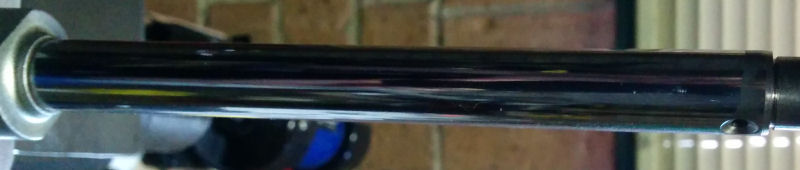
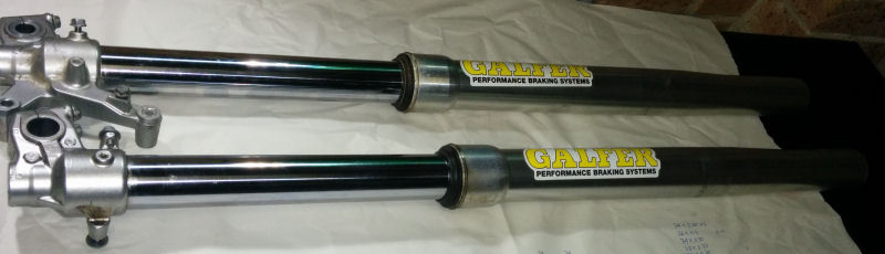
When I decided to do the revalving myself I expected the shock to be significantly more difficult than the forks. Boy, was I wrong! Maybe if I had limited myself to only doing the compression valving on the forks it would have been easier, but I decided to go the whole-hog doing buying the mid-valve kit which includes rebound as well. To start with, just removing the forks was easy enough and whilst the forks were on the bench it was very obvious that the inner tubes were very polished and reflective... this is not a good thing! It is meant so have a nice cross-hatching so that the fork seals don't leak. So that it going to need to be done before I put everything back together.
Removing the fork caps and the springs was relatively easy too - I already had the right size tools and because I had done it before to change the fork oil I was fairly comfortable doing that.
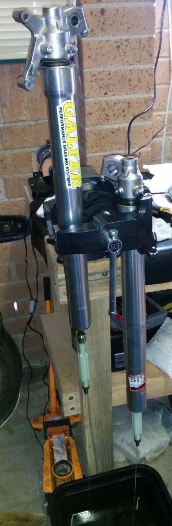
I hadn't removed the inner cartridges before though, so when I turned the forks upside down to remove the base valve I was surprised to see I needed an 8mm Allen Key/Hex socket rather than just a standard spanner. I managed to track one down but when I came to try removing the valve it just turned without undoing. After consulting Grant (at my local suspension tuning shop - Shock Treatment) he said I either needed to use a rattle-gun (impact wrench) to "break" the initial bite on the threads so that the cartridge inside the fork that the base valve screws into doesn't turn, or use a tool that slides down inside the fork tube and holds the base of the cartridge whilst undoing the base valve. I opted to get the tool because it can also be used to remove the midvalve (I think I am getting my part names correct - please forgive me if I am not though).
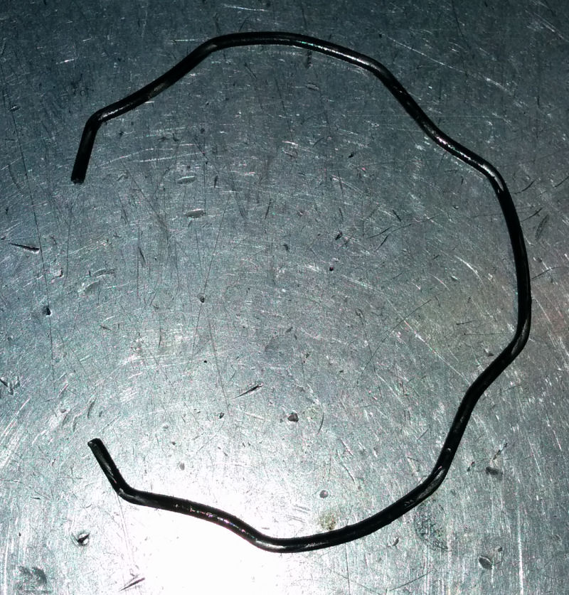
Once I removed the inner dampening rods from the fork tubes I went about trying to "slide hammer" the inner and outer fork tubes apart as per the Suspension Bible instructions - but after several attempts I was having no luck. I called Shock Treatment and Grant told me I needed to remove the circlip holding the fork dust seal inside the outer tube. Once I did that the tubes came apart with only 2 slide-hammerings. Sadly, my attempts to separate the tubes with the circlip still in place damaged the bushes which I don't have spares of. I should probably replace them anyway as they are still the ones that came on the bike when I bought it in 2010.
This is the base valve assembly off the bottom of the forks.
Taking the valve apart it is clear to see it is a pretty basic design with only a few shims and horribly small port holes in the plate nearest the spring.
When you compare the stock piston and the Gold Valve piston you can see how woefully inadequate the port holes on the stock valve are compared to the Racetech part which has pretty decent size ports. I believe the larger ports make the forks less likely to suffer from "compression spiking" where the fluid just cannot flow through the ports fast enough and so it effectively stops the forks compressing any further. With the larger ports allowing good flow of fluid you can control the damping much better using the shim stack which flexes based on the force of the fluid being forced through the ports. I find this all VERY interesting and I can see myself investigating this more to learn more.
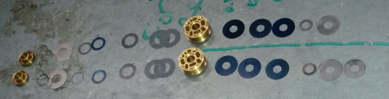
I then measured and laid out the new compression shim stack that Terry (from Shock Treatment) recommended.
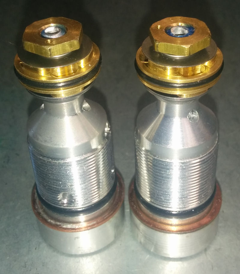
Now, although I have the shim stack sorted I am not sure which way it goes on the pistons. Here are the Gold Valve pistons each side of the new shim stack. Also, Terry recommended I drill a 1mm hole in the side of the piston to compensate for the fact that my forks have no rebound adjusters - so the hole provides a "free bleed" to allow oil to flow on rebound (I think). When I asked why he recommended a "permanent" solution by drilling a hole rather than opting for "Free Bleed Shims" each side of the piston (Free bleed shims are standard shims that are just a little smaller in diameter than the very outside edge of the piston ports so that fork oil can flow through the piston at slow speed without needing the shim stack to flex). My understanding is that "Free bleeds" are options of last resort because they allow totally uncontrolled flow... I think I'd like to learn a bit more about this subject.
So here is what I think is the correct assembly of the new base valve (Compression valve) stack but I am not 100% sure that I have the piston the correct way around.
What makes me think I have the piston the right way around is that the spring fits nicely into the recess in the piston (top left corner in the image below). What is confusing though is that the Racetech instructions say that on "some forks" the valving assembly is upside down without giving any real way of letting the Joe Sixpack without valving experience determine which way the valving needs to be. I am sure Grant and Terry will be able to set me on the right track though.
Removing the fork caps and the springs was relatively easy too - I already had the right size tools and because I had done it before to change the fork oil I was fairly comfortable doing that.
I hadn't removed the inner cartridges before though, so when I turned the forks upside down to remove the base valve I was surprised to see I needed an 8mm Allen Key/Hex socket rather than just a standard spanner. I managed to track one down but when I came to try removing the valve it just turned without undoing. After consulting Grant (at my local suspension tuning shop - Shock Treatment) he said I either needed to use a rattle-gun (impact wrench) to "break" the initial bite on the threads so that the cartridge inside the fork that the base valve screws into doesn't turn, or use a tool that slides down inside the fork tube and holds the base of the cartridge whilst undoing the base valve. I opted to get the tool because it can also be used to remove the midvalve (I think I am getting my part names correct - please forgive me if I am not though).
Once I removed the inner dampening rods from the fork tubes I went about trying to "slide hammer" the inner and outer fork tubes apart as per the Suspension Bible instructions - but after several attempts I was having no luck. I called Shock Treatment and Grant told me I needed to remove the circlip holding the fork dust seal inside the outer tube. Once I did that the tubes came apart with only 2 slide-hammerings. Sadly, my attempts to separate the tubes with the circlip still in place damaged the bushes which I don't have spares of. I should probably replace them anyway as they are still the ones that came on the bike when I bought it in 2010.
This is the base valve assembly off the bottom of the forks.
Taking the valve apart it is clear to see it is a pretty basic design with only a few shims and horribly small port holes in the plate nearest the spring.
When you compare the stock piston and the Gold Valve piston you can see how woefully inadequate the port holes on the stock valve are compared to the Racetech part which has pretty decent size ports. I believe the larger ports make the forks less likely to suffer from "compression spiking" where the fluid just cannot flow through the ports fast enough and so it effectively stops the forks compressing any further. With the larger ports allowing good flow of fluid you can control the damping much better using the shim stack which flexes based on the force of the fluid being forced through the ports. I find this all VERY interesting and I can see myself investigating this more to learn more.
I then measured and laid out the new compression shim stack that Terry (from Shock Treatment) recommended.
Now, although I have the shim stack sorted I am not sure which way it goes on the pistons. Here are the Gold Valve pistons each side of the new shim stack. Also, Terry recommended I drill a 1mm hole in the side of the piston to compensate for the fact that my forks have no rebound adjusters - so the hole provides a "free bleed" to allow oil to flow on rebound (I think). When I asked why he recommended a "permanent" solution by drilling a hole rather than opting for "Free Bleed Shims" each side of the piston (Free bleed shims are standard shims that are just a little smaller in diameter than the very outside edge of the piston ports so that fork oil can flow through the piston at slow speed without needing the shim stack to flex). My understanding is that "Free bleeds" are options of last resort because they allow totally uncontrolled flow... I think I'd like to learn a bit more about this subject.
So here is what I think is the correct assembly of the new base valve (Compression valve) stack but I am not 100% sure that I have the piston the correct way around.
What makes me think I have the piston the right way around is that the spring fits nicely into the recess in the piston (top left corner in the image below). What is confusing though is that the Racetech instructions say that on "some forks" the valving assembly is upside down without giving any real way of letting the Joe Sixpack without valving experience determine which way the valving needs to be. I am sure Grant and Terry will be able to set me on the right track though.
#8
07-26-2014, 10:24 PM
My attempts at doing the fork revalving during the week were unsuccessful because I was thwarted by my lack of knowledge of what I was looking for and looking at. So this morning I went over to Shock Treatment for some help. I knew for a start that I needed to buy new fork bushes as I had damaged mine when I had tried to slide-hammer the forks apart without first removing this circlip that help the seal in place.
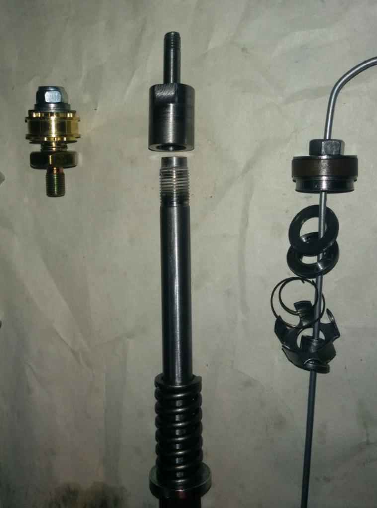
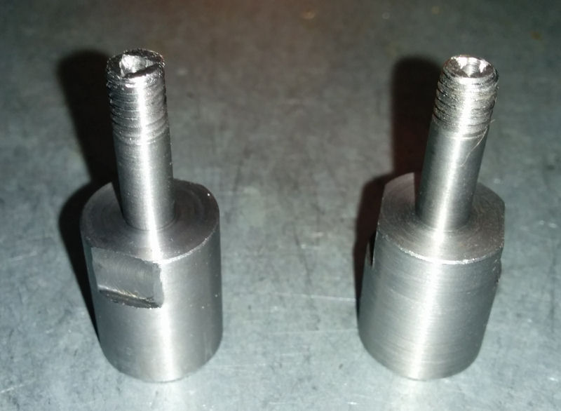
The thing that made me stop trying altogether was the damping rod end that holds the rebound valve. The Racetech kit came with an assembly that looked like it needed to be screwed into a hole at the end of the damping rod, but when I removed the damping rod end I found that there was a thread on the outside of the damping rod end rather than a threaded hole:
I was also a little confused by the fact that the instruction sheet in the Racetech kit only seemed to have a rebound shim stack whereas Terry had given me a mid-valve stack as well as a rebound stack... I didn't know whether the shim stacks perhaps went on opposite sides of the piston, but it turns out the mid stack goes on top of the rebound stack (I think).
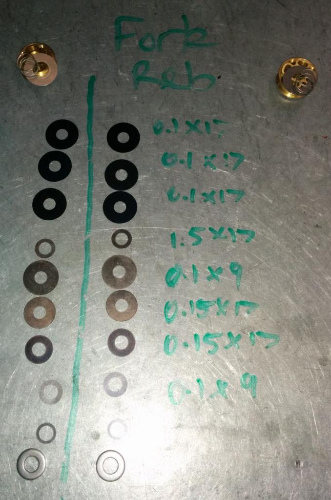
New mid stack laid out
New rebound stack laid out
Now, if I only had the rebound stack as the Racetech instructions catered for I probably could have just removed the stock rebound valving from the stock damping rod end and put the Gold valve kit on:
But because I had more shims the shaft on the damping rod end was not long enough so I had to remove the stock ones and bolt on a Racetech set that Shock Treatment had in stock. With the new valving stack and piston installed my damping rod headaches were solved
Now, because the forks on my KLX do not have any form of rebound adjustment, there is no rebound adjustment circuit to allow oil to flow back after a compression - so Terry had recommended drilling a 1mm hole in the side of the piston on one of the ports to make up for this. My problem is that I do not have a nice big drill press etc. to be able to do that so I was in favour of using free bleed shims on each side of the piston. Terry pointed out that the problem with that "solution" is that fluid can flow on all ports past the shim and it is really difficult to limit the flow to the small amount needed to compensate for the lack of a rebound adjustment circuit. So he kindly drilled the hole for me.
With that valve sorted it was just a case of curling the strip of seal material supplied in the kit into a tight coil, placing it on the outside of the piston and then quickly inserting the valve into the damping rod. There is a little step just on the inside of the damping rod which requires you to wiggle the piston around a bit to get the assembly to slide down. When I first attempted this job I didn't wiggle the valve enough so it caused a little scuffing on the edge of the seal material that Grant fixed for me.
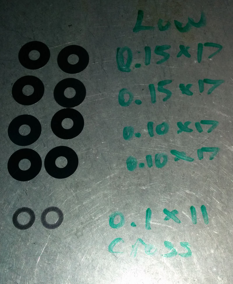
Onto the base valve! I first measured and laid out the Low speed compression shims
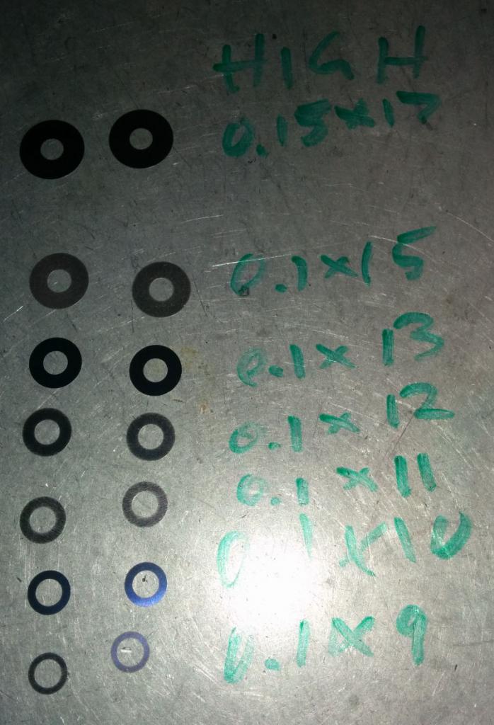
Then the High Speed shims
With the Low speed shim stack separated by a smaller diameter crossover shim I put the stack onto the midvalve shaft and went to bolt it down. Now, the instructions are VERY clear that this step must be 100% correct with no more than 25 inch-pounds of torque - NOT foot-pounds like I originally thought. Unfortunately I found out why this instruction exists when I over torqued the nut and broke off the end of the shaft! I think part of my problem was that I hadn't made sure the backing shim was properly centered so I ended up buckling the shim too.
http://i629.photobucket.com/albums/u...psfa768127.jpg
Now, I was VERY lucky that my kit was one of the very few that came with a threaded cap intended for cases where the valving stack does not leave enough thread for fit the cupped spacer needed to hold the spring and a nut at the same time. Because I had this part as well as a relatively small shim stack Grant could cut a bit more thread down on the shaft so there was enough thread for that little cupped nut to do the job without me needing to replace the base valve.
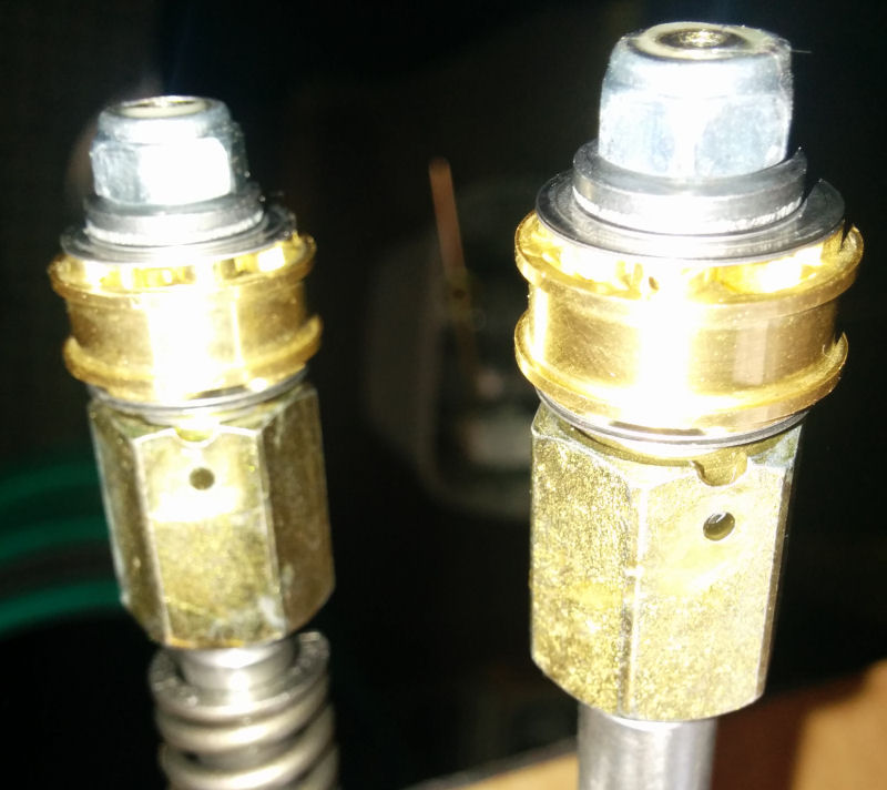
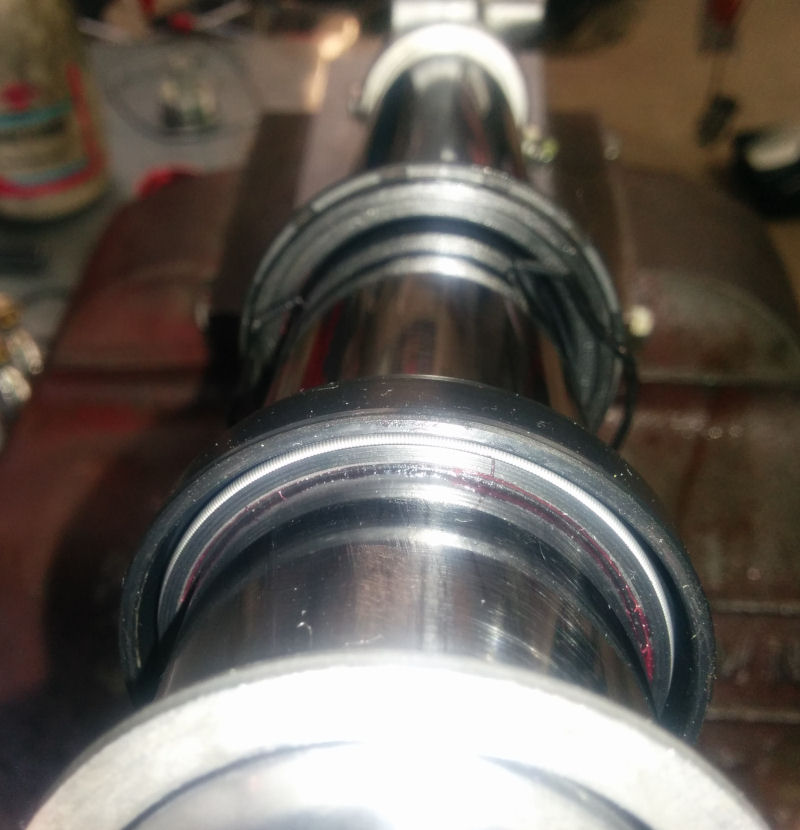
So the base valve was now ready, so we first secured the mid-valve in the top of the damping rod (the end without holes in the side of it) and then inserted the damping rod into the fork inner tube and screwed in the base valve. Oh, my inner tube was like glass is was so smooth and shiny which makes the seals leaking a distinct possibility. Grant "buffed" the tubes as best he could using some 400 grit sand paper and running it across the surface whist it turned in the lathe. He did point out that I need to consider re-chroming the tube as it needs it. With that done we greased the seals up and put then on the fork tube together with the dust seals, circlips and bushes. This is what it looked like:
Then it was a case of putting the inner tube into the outer tube and seating the bushes and seals using a seal driver. From this point onwards I felt pretty comfortable as I have changed the fork fluid before. I filled the lower/inner fork tubes with Motorex 5W fork oil, slowly pumped the damping rod up and down until no more air was bubbling up (topping up the oil level as needed) then sucking out oil from the top of the inner fork tube 100mm down from the edge. The insert the springs, pull up the damping rod and screw on the fork cap, then secure the fork caps into the outer fork tubes. DONE!
I cannot thank Terry and Grant at Shock Treatment for their patience with me, for all the advice and assistance they gave me, and for fixing my stuff-ups. It would have been quicker, cheaper, and easier for both them and for me if I had just left the job in their capable hands - but I wanted to learn how to do it myself and they indulged me and helped me. From my experience doing this job myself (with plenty of expert assistance) has shown me that you get VERY good value for money out of letting the experts with experience and knowledge to sort your suspension out. I think I would happily attack doing the shock again myself, but I would hesitate to attempt the forks again.
The thing that made me stop trying altogether was the damping rod end that holds the rebound valve. The Racetech kit came with an assembly that looked like it needed to be screwed into a hole at the end of the damping rod, but when I removed the damping rod end I found that there was a thread on the outside of the damping rod end rather than a threaded hole:
I was also a little confused by the fact that the instruction sheet in the Racetech kit only seemed to have a rebound shim stack whereas Terry had given me a mid-valve stack as well as a rebound stack... I didn't know whether the shim stacks perhaps went on opposite sides of the piston, but it turns out the mid stack goes on top of the rebound stack (I think).
New mid stack laid out
New rebound stack laid out
Now, if I only had the rebound stack as the Racetech instructions catered for I probably could have just removed the stock rebound valving from the stock damping rod end and put the Gold valve kit on:
But because I had more shims the shaft on the damping rod end was not long enough so I had to remove the stock ones and bolt on a Racetech set that Shock Treatment had in stock. With the new valving stack and piston installed my damping rod headaches were solved
Now, because the forks on my KLX do not have any form of rebound adjustment, there is no rebound adjustment circuit to allow oil to flow back after a compression - so Terry had recommended drilling a 1mm hole in the side of the piston on one of the ports to make up for this. My problem is that I do not have a nice big drill press etc. to be able to do that so I was in favour of using free bleed shims on each side of the piston. Terry pointed out that the problem with that "solution" is that fluid can flow on all ports past the shim and it is really difficult to limit the flow to the small amount needed to compensate for the lack of a rebound adjustment circuit. So he kindly drilled the hole for me.
With that valve sorted it was just a case of curling the strip of seal material supplied in the kit into a tight coil, placing it on the outside of the piston and then quickly inserting the valve into the damping rod. There is a little step just on the inside of the damping rod which requires you to wiggle the piston around a bit to get the assembly to slide down. When I first attempted this job I didn't wiggle the valve enough so it caused a little scuffing on the edge of the seal material that Grant fixed for me.
Onto the base valve! I first measured and laid out the Low speed compression shims
Then the High Speed shims
With the Low speed shim stack separated by a smaller diameter crossover shim I put the stack onto the midvalve shaft and went to bolt it down. Now, the instructions are VERY clear that this step must be 100% correct with no more than 25 inch-pounds of torque - NOT foot-pounds like I originally thought. Unfortunately I found out why this instruction exists when I over torqued the nut and broke off the end of the shaft! I think part of my problem was that I hadn't made sure the backing shim was properly centered so I ended up buckling the shim too.
http://i629.photobucket.com/albums/u...psfa768127.jpg
Now, I was VERY lucky that my kit was one of the very few that came with a threaded cap intended for cases where the valving stack does not leave enough thread for fit the cupped spacer needed to hold the spring and a nut at the same time. Because I had this part as well as a relatively small shim stack Grant could cut a bit more thread down on the shaft so there was enough thread for that little cupped nut to do the job without me needing to replace the base valve.
So the base valve was now ready, so we first secured the mid-valve in the top of the damping rod (the end without holes in the side of it) and then inserted the damping rod into the fork inner tube and screwed in the base valve. Oh, my inner tube was like glass is was so smooth and shiny which makes the seals leaking a distinct possibility. Grant "buffed" the tubes as best he could using some 400 grit sand paper and running it across the surface whist it turned in the lathe. He did point out that I need to consider re-chroming the tube as it needs it. With that done we greased the seals up and put then on the fork tube together with the dust seals, circlips and bushes. This is what it looked like:
Then it was a case of putting the inner tube into the outer tube and seating the bushes and seals using a seal driver. From this point onwards I felt pretty comfortable as I have changed the fork fluid before. I filled the lower/inner fork tubes with Motorex 5W fork oil, slowly pumped the damping rod up and down until no more air was bubbling up (topping up the oil level as needed) then sucking out oil from the top of the inner fork tube 100mm down from the edge. The insert the springs, pull up the damping rod and screw on the fork cap, then secure the fork caps into the outer fork tubes. DONE!
I cannot thank Terry and Grant at Shock Treatment for their patience with me, for all the advice and assistance they gave me, and for fixing my stuff-ups. It would have been quicker, cheaper, and easier for both them and for me if I had just left the job in their capable hands - but I wanted to learn how to do it myself and they indulged me and helped me. From my experience doing this job myself (with plenty of expert assistance) has shown me that you get VERY good value for money out of letting the experts with experience and knowledge to sort your suspension out. I think I would happily attack doing the shock again myself, but I would hesitate to attempt the forks again.
#9
07-26-2014, 11:42 PM
Yes, it's interesting how people think there's more mystery with the shock revalve/rebuild than the fork. I've always found the shock to be generally more simple than the fork. Looks like you got some good advice and a quality finished product. It will make a difference.
#10
07-26-2014, 11:53 PM
Unfortunately I didn't think to ask what clicker setting I should start from so I will just middle them all and go from there.
With the shock, looking closely at the stock piston and the Racetech Gold Valve piston, in my non-expert and uninformed opinion there is not a great deal of difference in the port sizes... so I would think the stock valving really would benefit greatly from an improved shim stack to give an overall improvement in the operation of the shock. Of course, the secret is in knowing what changes are needed to the shim stack.
I am looking forward to the first time I can take the bike on dirt to see how it goes.
Based on advice from a learned mate I tracked down a copy of a Honda CR workshop manual and read through the "Suspension Adjustment Guidelines" section. It has some VERY useful advice for tuning your suspension based on various terrain and handling symptoms. I have copied and pasted the relevant section below for other forum members. The full Honda CR250R manual can be downloaded here. Look at page 104 (in the PDF, the page 99 of the printer manual):
http://owners.honda.com/assets/owner...007_cr250r.pdf
Suspension Adjustments for Track Conditions
Soft Surface
Hard-surfaced track: Begin with the standard setting. If the suspension is too stiff/soft, adjust according to the Table below.
Sand track: Adjust to a stiffer position. e.g. Turn the compression damping adjuster to a stiffer position (turn adjuster clockwise). Alternatively, install a stiffer spring.
Mud track: Adjust to a stiffer position because mud build-up increases your bike's weight. e.g. Turn the compression damping adjuster to a stiffer setting (turn adjuster clockwise). Alternatively, install a stiffer spring.
Adjustments for too soft forks:
Rear Suspension Adjustment Adjustments for Type of Track
Hard-surfaced track: Begin with the standard settings. If the suspension is too stiff/soft, adjust according to the table below.
Sand track: Lower the rear end (to improve front wheel stability) by increasing Race Sag (reduce spring preload). e.g. Turn the compression damping adjuster and, especially, rebound damping adjuster to a stiffer setting. Increase standard Race Sag 5mm to 10mm.
Mud track: Adjust to a stiffer position because mud build-up increases your bike's weight. e.g. Adjust the compression and rebound damping adjusters to stiffer settings. Install the optional stiff spring. Reduce standard Race Sag 5mm to 10mm.
Adjustments for stiff rear suspension:
Soft Surface
On soft ground, sand, and especially mud, consider increasing compression damping front and rear.
Sand often requires a bit more rebound damping to minimize rear end kick. Although sand bumps are usually larger, there?s more distance between them, giving the shock more time to recover.
You may want a little bit stiffer front suspension for sand tracks to help keep the front end up and improve straight-line stability.
In a muddy event, stiffer aftermarket springs front and rear may help, especially if you are heavier than the average rider. Your CR may be undersprung because of the added weight of the clinging mud. This additional weight may compress the suspension too much and affect traction.
Hard SurfaceSand often requires a bit more rebound damping to minimize rear end kick. Although sand bumps are usually larger, there?s more distance between them, giving the shock more time to recover.
You may want a little bit stiffer front suspension for sand tracks to help keep the front end up and improve straight-line stability.
In a muddy event, stiffer aftermarket springs front and rear may help, especially if you are heavier than the average rider. Your CR may be undersprung because of the added weight of the clinging mud. This additional weight may compress the suspension too much and affect traction.
For a fast, hard track with no large jumps, you can probably run the same spring as normal, but run softer damping both ways-compression and rebound. If you run softer rebound damping, the wheel will follow the rough ground and small bumps much better, and you will hook up better. With a lot of rebound damping, the wheel returns very slowly and doesn't contact the ground quickly enough after each bump. The result is a loss of traction and slower lap times
Front Suspension Adjustment Adjustments for Type of TrackHard-surfaced track: Begin with the standard setting. If the suspension is too stiff/soft, adjust according to the Table below.
Sand track: Adjust to a stiffer position. e.g. Turn the compression damping adjuster to a stiffer position (turn adjuster clockwise). Alternatively, install a stiffer spring.
Mud track: Adjust to a stiffer position because mud build-up increases your bike's weight. e.g. Turn the compression damping adjuster to a stiffer setting (turn adjuster clockwise). Alternatively, install a stiffer spring.
Adjustments for too soft forks:
Initial travel too soft symptom: Steering is too quick. Front end darts while cornering or riding in a straight line.
Initial travel too soft action: Test stiffer compression damping adjustments. Test stiffer rebound damping adjustments.
Middle travel too soft symptom: Front end dives when cornering.
Middle travel too soft action: If suspension isn?t stiff in initial travel then test stiffer compression damping adjustments. If initial travel becomes stiff because of this adjustment then reduce the rebound damping, test softer compression damping adjustments, and if that doesn't solve the problem, install a stiffer spring.
Final travel too soft symptom: Bottoms on landings. Bottoms on large bumps, especially downhill bumps.
Final travel too soft action: If initial and middle travel aren't stiff, then test stiffer compression damping adjustments. If initial and middle travel are stiff, then install a stiffer spring. If initial travel is stiff after installing a stiffer spring, then test softer compression damping adjustments. If initial travel is still soft after installing a stiffer spring, then test stiffer compression damping adjustments. If final travel is still soft after installing a stiffer spring, then increase the fork oil level in increments of 5ml.
Entire travel too soft symptom: Front end shakes. Fork bottoms over any type of terrain.
Entire travel too soft action: Install stiffer spring. Test stiffer compression damping adjustments. Increase rebound damping.
Adjustments for too stiff forks:Initial travel too soft action: Test stiffer compression damping adjustments. Test stiffer rebound damping adjustments.
Middle travel too soft symptom: Front end dives when cornering.
Middle travel too soft action: If suspension isn?t stiff in initial travel then test stiffer compression damping adjustments. If initial travel becomes stiff because of this adjustment then reduce the rebound damping, test softer compression damping adjustments, and if that doesn't solve the problem, install a stiffer spring.
Final travel too soft symptom: Bottoms on landings. Bottoms on large bumps, especially downhill bumps.
Final travel too soft action: If initial and middle travel aren't stiff, then test stiffer compression damping adjustments. If initial and middle travel are stiff, then install a stiffer spring. If initial travel is stiff after installing a stiffer spring, then test softer compression damping adjustments. If initial travel is still soft after installing a stiffer spring, then test stiffer compression damping adjustments. If final travel is still soft after installing a stiffer spring, then increase the fork oil level in increments of 5ml.
Entire travel too soft symptom: Front end shakes. Fork bottoms over any type of terrain.
Entire travel too soft action: Install stiffer spring. Test stiffer compression damping adjustments. Increase rebound damping.
Initial travel too stiff symptoms: Stiff on small bumps while riding at full throttle in a straight line. Stiff on small cornering bumps. Front end wanders while riding at full throttle in a straight line.
Initial travel too stiff actions: Test softer compression damping adjustments. Reduce the rebound damping adjustments. Check for dirt in the dust seals. Check the fork oil for any contamination. If the front end dives while cornering, reduce the rebound damping, and if that doesn't solve the problem, install a stiffer spring. If a stiffer spring makes the suspension too stiff over the full range of travel then test softer compression damping adjustments until the desired compression damping for initial travel is obtained.
Middle travel too stiff symptoms: Stiff on bumps when cornering. Front end wanders when cornering. Stiff suspension on bumps, especially downhill bumps. While braking, front end dives during initial travel, then feels stiff.
Middle travel too stiff actions: If initial travel isn't stiff then test stiffer compression damping adjustments (This should produce smooth fork action from initial to middle travel). If initial and middle travel is stiff then test softer compression damping adjustments, and/or reduce the rebound damping.
Final travel too stiff symptoms: Doesn't bottom on landings, but feels stiff. Stiff on large bumps, especially downhill bumps. Stiff on large bumps when cornering.
Final travel too stiff actions: If initial and middle travel aren't stiff then test stiffer compression damping adjustments (This should produce smooth fork action from initial to middle travel). If final travel is still stiff after this, or if initial and middle travel becomes stiff then install a softer spring. Test softer compression damping adjustment. If the entire travel feels stiff after this then test softer compression damping adjustments until the desired initial travel compression damping is obtained. Lower the oil level by 5ml.
Entire travel too stiff symptom: Stiff suspension on any type of terrain
Entire travel too stiff actions: Test softer compression damping adjustments. Reduce the rebound damping. Lower the oil level by 5ml.
Rear Suspension Adjustment Adjustments for Type of Track
Hard-surfaced track: Begin with the standard settings. If the suspension is too stiff/soft, adjust according to the table below.
Sand track: Lower the rear end (to improve front wheel stability) by increasing Race Sag (reduce spring preload). e.g. Turn the compression damping adjuster and, especially, rebound damping adjuster to a stiffer setting. Increase standard Race Sag 5mm to 10mm.
Mud track: Adjust to a stiffer position because mud build-up increases your bike's weight. e.g. Adjust the compression and rebound damping adjusters to stiffer settings. Install the optional stiff spring. Reduce standard Race Sag 5mm to 10mm.
Adjustments for stiff rear suspension:
- Symptom: Suspension feels stiff on small bumps
- Actions: Test softer low speed compression. If it still feels stiff, further test softer low and high speed compression adjustments simultaneously.
- Symptom: Suspension feels stiff on large bumps
- Actions: Test softer high speed compression. If it still feels stiff, further test softer low and high speed compression adjustments simultaneously.
- Symptom: Entire travel too stiff
- Actions: Test softer high and low speed compression adjustments and rebound adjustment simultaneously. If it still feels stiff, replace the spring with a softer spring and begin with the standard settings to softer settings
Adjustments for soft rear suspension:- Actions: Test softer low speed compression. If it still feels stiff, further test softer low and high speed compression adjustments simultaneously.
- Symptom: Suspension feels stiff on large bumps
- Actions: Test softer high speed compression. If it still feels stiff, further test softer low and high speed compression adjustments simultaneously.
- Symptom: Entire travel too stiff
- Actions: Test softer high and low speed compression adjustments and rebound adjustment simultaneously. If it still feels stiff, replace the spring with a softer spring and begin with the standard settings to softer settings
- Symptom: Entire travel too soft
- Actions: Test stiffer high and low speed compression adjustments simultaneously. If it still feels soft, replace the spring with a stiffer spring and begin with the standard settings to stiffer setting
- Symptom: Rear end sways
- Actions: Test stiffer high and low speed compression adjustments and rebound adjustment to stiffer settings simultaneously
Adjustments for suspension that bottoms:- Actions: Test stiffer high and low speed compression adjustments simultaneously. If it still feels soft, replace the spring with a stiffer spring and begin with the standard settings to stiffer setting
- Symptom: Rear end sways
- Actions: Test stiffer high and low speed compression adjustments and rebound adjustment to stiffer settings simultaneously
- Symptom: Suspension bottoms at landing after jumping
- Actions: Test stiffer high speed compression. If it still bottoms, test stiffer high and low speed compression adjustments, and replace the spring with a
stiffer spring if necessary.
- Symptom: Suspension bottoms after landing
- Actions: Test stiffer low speed compression adjustment. If it still bottoms, test stiffer high and low speed compression adjustments, and replace the spring with a stiffer spring if necessary
- Symptom: Suspension bottoms after end of continuous bumps
- Actions: Test softer rebound dumping adjustment. If it still bottoms, test stiffer high and low speed compression adjustments and softer rebound damping adjustment, and replace the spring with a stiffer spring if necessary.

